
Galant LS V6-3.0L SOHC (1999)
<When using a voltmeter>
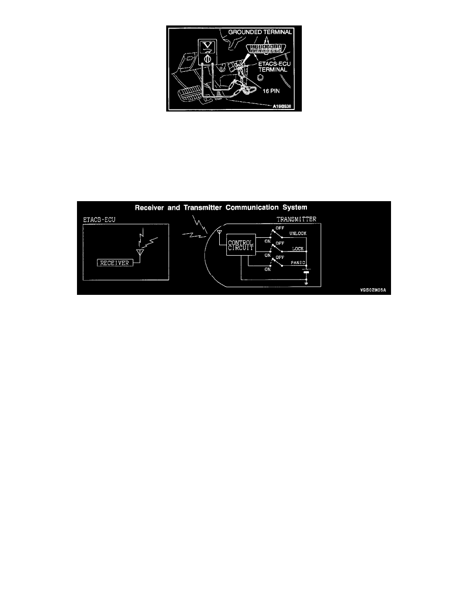
1. Use special tool MB991529 to connect a voltmeter between ground terminal 4 or 5 and ETACS-ECU terminal 9 of the data link connector.
2. Check that the voltmeter indicator deflects once when the input signal enters.
If one of the input signal checks shows a defect, check the relevant input circuit.
If all of the input signal checks show no defect, replace the ETACS-ECU or front-ECU.
The power window timer function should work normally.
Inspection Procedure E-1
Receiver And Transmitter Communication System
CIRCUIT OPERATION
Receiver within the ETACS-ECU receives the lock/unlock signal from the transmitter.
TECHNICAL DESCRIPTION (COMMENT)
The cause may be a malfunction of the receiver and transmitter communication system.
TROUBLESHOOTING HINTS
-
Malfunction of the ETACS-ECU
-
Malfunction of the transmitter
DIAGNOSIS
Required Special Tools:
MB991223: Test Harness Set
MB991502: Scan Tool (MUT-II)
MB991529: Diagnostic Trouble Code Check Harness
STEP 1. Check the central door locking system operation.
If the central door locking system does not work normally, solve the problem first.
If the central door locking system works normally, go to Step 2.
STEP 2. Check the input signal.
Check the input signals from the transmitter switches.