
Galant VR4 AWD L4-1997cc 2.0L DOHC Turbo (1992)
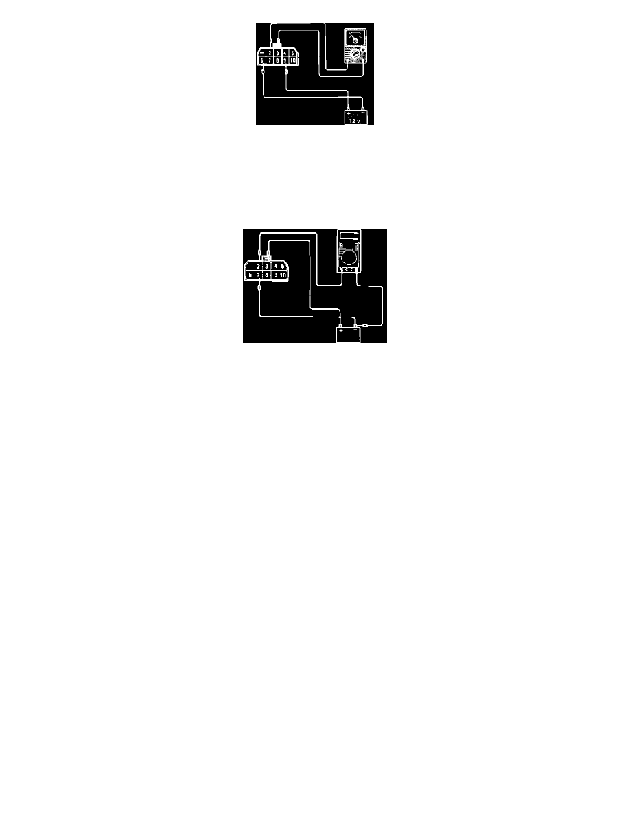
Fig. 2 Relay Test
2. Supply 12 VDC to relay terminals 6 (-) and 9 (+). Using an Ohmmeter, check for continuity between terminals 2 and 3. Refer to Fig. 2.
Continuity:
-
Should exist when Voltage is supplied.
-
Should NOT exist when Voltage is NOT supplied.
Fig. 3 Relay Test
3. Supply 12 VDC to relay terminals 7 (-) and 3 (+). Using a Voltmeter, check for Voltage between terminals 2 (+) and supply battery ground
terminal. Refer to Fig. 3.
Voltage:
-
12 VDC when terminal 7 is connected.
-
0 VDC when terminal 7 is NOT connected.
HARNESS TEST
1. Disconnect the negative battery cable and the ECU connector.
2. Reconnect the negative battery cable and turn the key to the ON position.
3. Using a Volt meter, check the Voltage between ECU harness terminal 110 and ground.
Voltage: ............................................................................................................................................................................................ System Voltage
4. Turn the key to the OFF position.
5. Disconnect the control relay connector.
6. Using an Volt meter, check the Voltage between relay harness terminal 10 and ground.
Voltage: ............................................................................................................................................................................................ System Voltage
7. Using a Ohm meter, check for continuity between relay harness terminal 8 and ECU harness connector terminals 63 and 66.
Continuity: ............................................................................................................................................................................................ Should exist
8. Using a Ohm meter, check for continuity between relay harness terminal 5 and ECU harness connector terminals 102 and 107.
Continuity: ............................................................................................................................................................................................ Should exist
9. Using a Ohm meter, check for continuity between relay harness terminal 4 and ECU harness connector terminals 102 and 107.
Continuity: ............................................................................................................................................................................................ Should exist
If any of the previous tests produce unsatisfactory results, the harness will need to be repaired or replaced. Once repairs have been completed, road
test the vehicle to confirm that the repair has corrected the problem.
If the same problem reoccurs, it is possible that there is an intermittent failure of the component or the ECU. Check for looseness at all harness