
Lancer LS L4-2.0L SOHC (2002)
STEP 4. Check the combination meter (printed-circuit board).
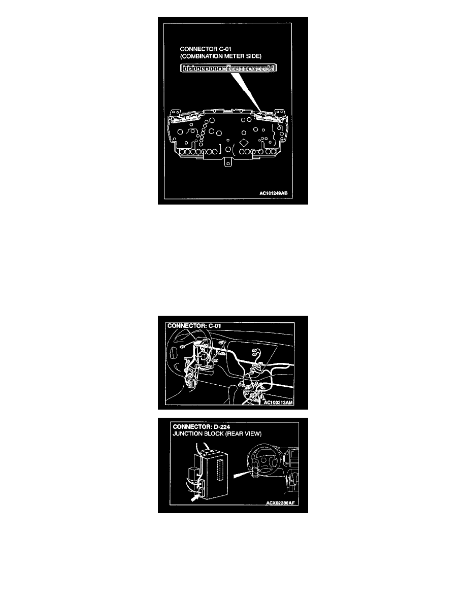
1. Remove the combination meter.
2. Remove the high-beam indicator light bulb. Then measure the resistance value between the bulb terminals.
3. Install the bulb to the combination meter, and then measure the resistance value between connector C-01 terminals 4 and 5. The measured
resistance value should be roughly the same as the value measured in Step 2.
Q: Are these two resistance values extremely different?
YES: Repair or replace the combination meter (printed circuit board). Check that the headlight-beam indicator light illuminates normally.
NO (roughly the same): Go to Step 5
STEP 5. Check combination meter connector C-01 and ETACS-ECU connector C-228 for damage.
Q: Are combination meter connector C-01 and ETACS-ECU connector C-228 in good condition?
YES: Go to Step 6
NO: Repair or replace the connector. Refer to Harness Connector Inspection. Check that the high-beam indicator light illuminates normally.