
Lancer LS L4-2.0L SOHC (2002)
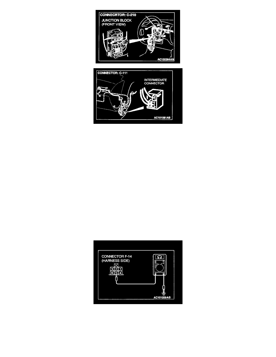
STEP 29. Check the wiring harness between side turn-signal light (RH) connector A-01 and ETACS-ECU connector C-226.
NOTE: Also check junction block connector C-210 and intermediate connector C-111. If junction block connector C-210 or intermediate connector
C-111 is damaged, repair or replace the connector as described in Harness Connector Inspection.
Q: Is the wiring harness between side turn-signal light (RH) connector A-01 and ETACS-ECU connector C-226 in good condition?
YES: Replace the socket. Check that the turn-signal lights illuminate normally.
NO: Repair the wiring harness. Check that the turn-signal lights illuminate normally.
STEP 30. Check the rear turn-signal light bulb (LH).
1. Remove the rear turn-signal (LH) light bulb.
2. Check that the rear turn-signal light bulb (LH) is not broken.
Q: Is the rear turn-signal (LH) light bulb in good condition?
YES: Go to Step 31.
NO: Replace the rear turn-signal (LH) light bulb. Check that the turn-signal lights illuminate normally.
STEP 31. Measure at rear combination light (LH) connector F-14 in order to check the ground circuit to the rear combination light (LH).
1. Disconnect rear combination light (LH) connector F-14, and measure at the wiring harness side.
2. Measure the resistance value between terminal 5 and ground.
-
The measured value should be 2 Ohm or less.
Q: Does the measured resistance value correspond with this range?