
Lancer LS L4-2.0L SOHC (2002)
Required Special Tools:
-
MB991223: Test Harness Set
-
MB991502: Scan Tool (MUT-II)
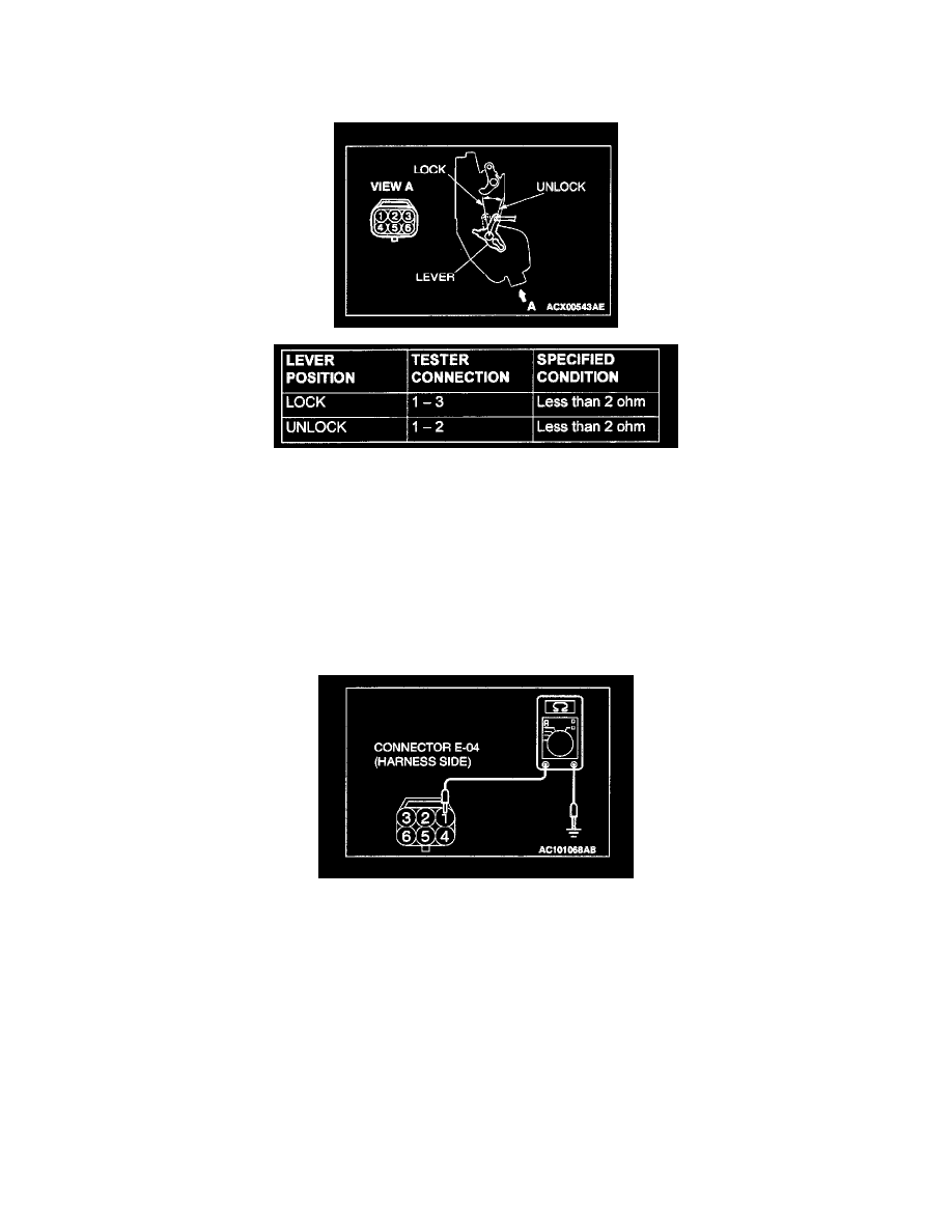
STEP 1. Check the driver's door lock actuator switch.
Disconnect driver's door lock actuator switch connector E-04.
Then check continuity between the switch terminals.
Q: Is the driver's door lock actuator switch in good condition?
YES: Go to Step 2.
NO: Replace the driver' door lock actuator switch. If the functions, which are described in "CIRCUIT OPERATION", work normally, the input signal
from the driver's door lock actuator switch should be normal.
STEP 2. Measure at driver's door lock actuator switch connector E-04 in order to check the ground circuit to the driver's door lock actuator
switch.
1. Disconnect driver's door lock actuator switch connector E-04, and measure at the harness side.
2. Measure the resistance value between terminal 1 and ground.
-
The measured value should be 2 Ohm or less.
Q: Does the measured resistance value correspond with this range?
YES: Go to Step 5.
NO: Go to Step 3.