
Mirage L4-1468cc 1.5L SOHC 12 Valve (1996)
SRS Control Unit: Testing and Inspection
Repair Procedure
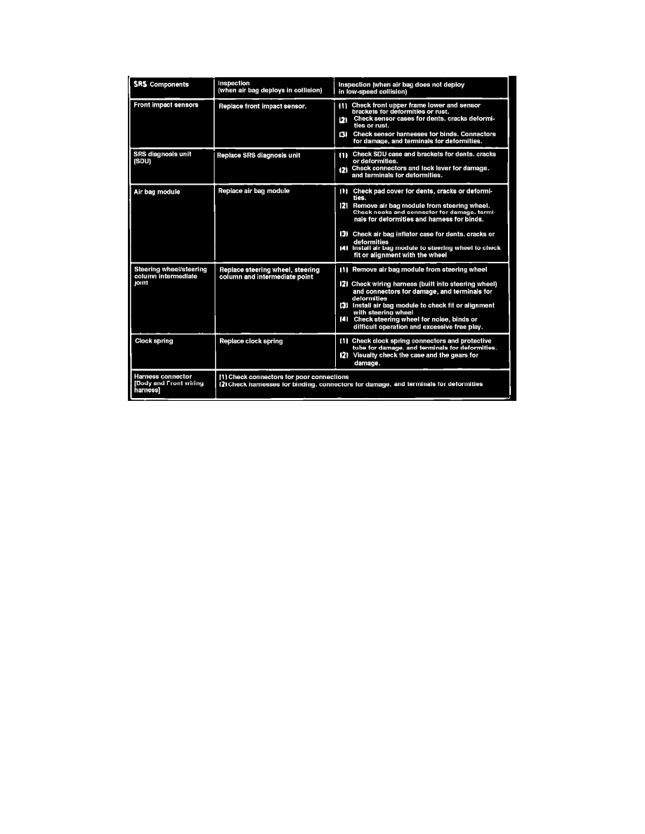
Fig. 10 Component Inspection Chart
1.
If airbag deployed in the collision, remove the deployed air bag module.
2.
Check the SRS components using table shown in Fig. 10.
3.
If the SRS components are showing any visible damage such as dents, cracks or deformation, replace as necessary.
4.
Conduct self-diagnosis using multi-use tester to ensure entire SRS operates properly except open circuit of airbag module.
5.
Install new airbag module.
To inspect and service the SRS after a collision (whether or not the air bags have deployed), perform the following steps.
SRS-ECU MEMORY CHECK
1. Connect the scan tool to the data link connector 1(16-pin).
CAUTION: Turn off ignition switch before connecting or disconnecting the scan tool.
2. Read (and write down) all displayed diagnostic trouble codes.
NOTE: If the battery power supply has been disconnected or disrupted by the collision, the scan tool cannot communicate with the SRS-ECU.
Check the battery then inspect and, if necessary, repair the body wiring harness before proceeding.
3. Read the data list (fault duration and how many times memories are erased) using the scan tool.
4. Erase the diagnostic trouble codes and after waiting 5 seconds or more read (and write down) all displayed diagnostic trouble codes.