
Mirage L4-1468cc 1.5L SOHC 12 Valve (1996)
Power Steering Pump: Service and Repair
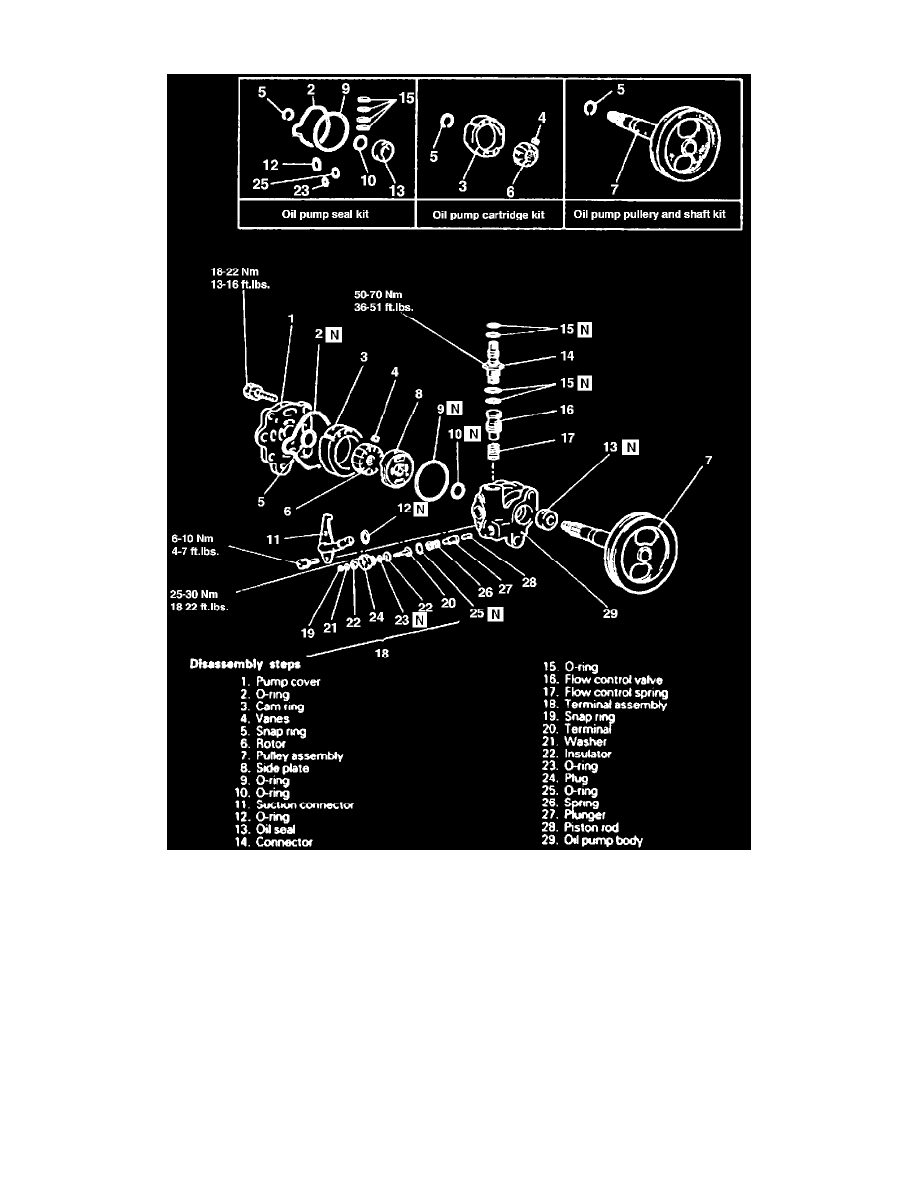
Fig. 39 Exploded View Of Power Steering Pump
1. Disassemble power steering pump in numbered sequence shown in Fig. 39.
2. Measure gap between vane and rotor. Gap limit is 0.0024 inch.
3. Using a dial gauge at the end of the pump shaft, move pulley up and down and ensure movement is less than 0.004 inch.
4. Reverse numbered sequence shown in Fig. 39 to assemble, noting the following:
a. Install piston rod spring into pump body with larger diameter end at terminal assembly side.
b. Apply Dexron II or Diamond ATF SP ATF to O-rings, flow control valve, rotor vanes and cam ring prior to installation.
c. Drive pulley shaft oil seal into pump body using suitable seal installation tool.
d. Align dowel pin of pump body with dowel pin hole of side plate to install side plate.
e. Install rotor onto pulley assembly so that rotor punch mark is at pump cover side.
f.
Ensure rotor snap is properly installed.
g. Align dowel pin of pump body with dowel holes of cam ring, then install so that cam ring's punch mark is at pump body side.