
Mirage L4-1597cc 1.6L DOHC (1990)
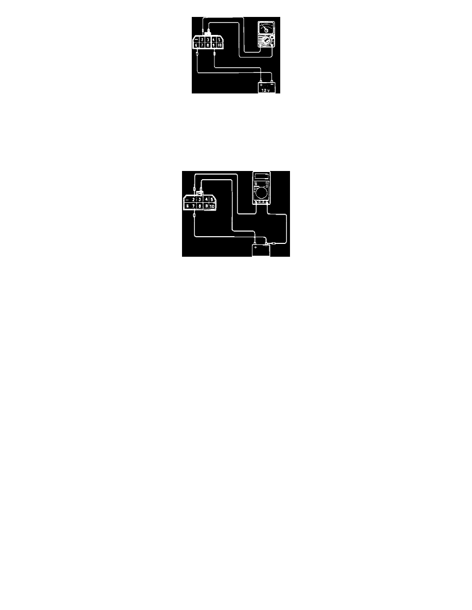
Fig. 2 Relay Test
2. Supply 12 vdc to relay terminals 6 (-) and 9 (+). Using an ohmmeter, check for continuity between terminals 2 and 3. Refer to Fig. 2.
Continuity
Should exist when voltage is supplied.
Should NOT exist when voltage is NOT supplied.
Fig. 3 Relay Test
3. Supply 12 vdc to relay terminals 7 (-) and 3 (+). Using a voltmeter, check for voltage between terminals 2 (+) and supply battery ground terminal.
Refer to Fig. 3.
Voltage
12 vdc when terminal 7 is connected.
0 vdc when terminal 7 is NOT connected.
HARNESS TEST
1. Disconnect the negative battery cable and the ECU connector.
2. Reconnect the negative battery cable and turn the key to the ON position.
3. Using a volt meter, check the voltage between ECU harness terminal 110 and ground.
Voltage
System voltage.
4. Turn the key to the OFF position.
5. Disconnect the control relay connector.
6. Using an volt meter, check the voltage between relay harness terminal 10 and ground.
Voltage
System voltage.
7. Using a ohm meter, check for continuity between relay harness terminal 8 and ECU harness connector terminals 63 and 66.
Continuity
Should exist.
8. Using a ohm meter, check for continuity between relay harness terminal 5 and ECU harness connector terminals 102 and 107.
Continuity
Should exist.
9. Using a ohm meter, check for continuity between relay harness terminal 4 and ECU harness connector terminals 102 and 107.
Continuity