
Mirage L4-1597cc 1.6L DOHC Turbo (1989)
Engine Control Module: Description and Operation
Engine Control Module (ECM)
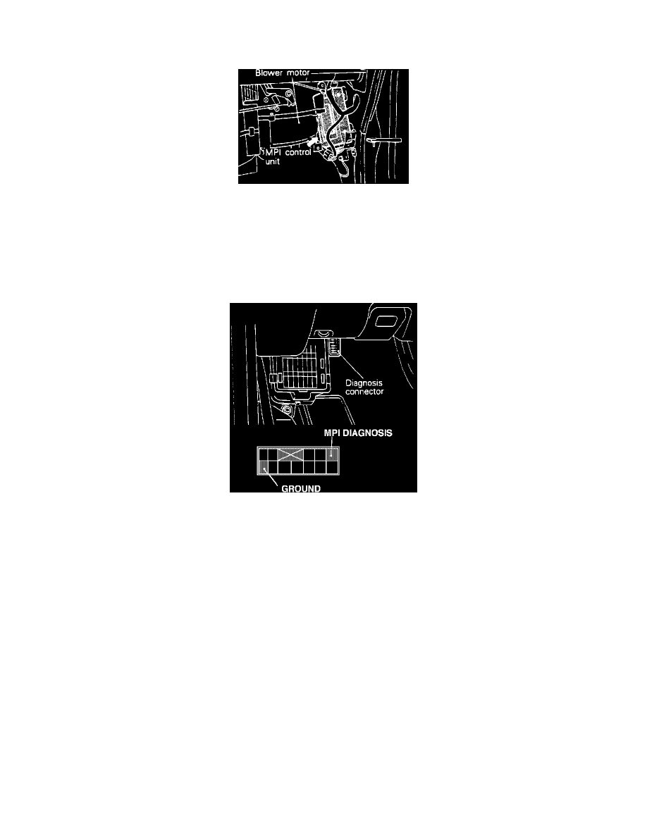
MPI Control Unit Location
The ECU consists of an 8-bit microprocessor, random access memory (RAM), read only memory (ROM) and Input/output (I/0) interface. Based on the
information from the input sensors, the ECU determines the optimum control for the operating conditions and drives the output actuators accordingly.
The ECU actively controls the operation of the Fuel Injection system, the Ignition timing, and has full control of the Idle Speed Control system.
Additionally the ECU interrupts the operation of the Air Conditioning and EGR systems under some conditions and controls the power to the Fuel Pump
and turbo wastegate solenoid. In addition to this, the system monitors the input/output signals to the engine control unit (some signals at all times and
others under specific conditions).
Diagnostic Connector
In the event improper operation is detected the ECU will store an error code or codes indicating which component or circuit has failed. The codes can
then be extracted from the self-diagnosis output terminal. There are 14 diagnosis items including the Normal State. The diagnosis results can be read out
with a voltmeter or multi-use tester. Since memorization of the trouble codes is backed up directly by the battery, the diagnosis results are held in
memory even if the ignition key is turned off. Be sure to extract the codes before disconnecting the battery as the trouble codes will be erased when the
battery terminal or the engine control unit connector is disconnected for more than 10 seconds.