
Mirage L4-1597cc 1.6L DOHC Turbo (1989)
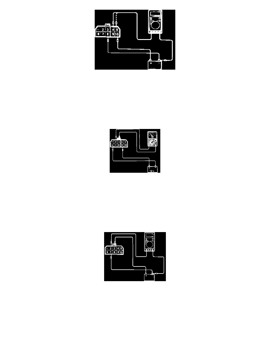
Fig. 1 Relay Test
1. Connect jumper wires between relay terminals 10 and 8 and a 12v power source. Terminal 10 is positive (+) and 8 is negative (-).
2. Measure the voltage at terminals 4 and 5 with the power connected and disconnected at terminal 8.
POWER TO RELAY ..................................................................................................................................... VOLTAGE READING TERMINALS 4 & 5
On ................................................................................................................................................................................................................. System Voltage
Off .............................................................................................................................................................................................................................. 0 Volts
Fig. 2 Relay Test
3. Connect jumper wires between relay terminals 9 and 6 and a 12v power source. Terminal 9 is positive (+) and 6 is negative (-).
4. Check for continuity at terminals 2 and 3 with the power connected and disconnected at terminal 6.
POWER TO RELAY ............................................................................................................................... CONTINUITY READING TERMINALS 2 & 3
On ......................................................................................................................................................................................................................... Continuity
Off ................................................................................................................................................................................................................... No Continuity
Fig. 3 Relay Test
5. Connect jumper wires between relay terminals 3 and 7 and a 12v power source. Terminal 3 is positive (+) and 7 is negative (-).
6. Measure the voltage at terminal 2 with the power connected and disconnected at terminal 7.
POWER TO RELAY .............................................................................................................................................. VOLTAGE READING TERMINAL 2
On ................................................................................................................................................................................................................. System Voltage
Off .............................................................................................................................................................................................................................. 0 Volts