
Mirage L4-1597cc 1.6L DOHC Turbo (1989)
Component Test
1.
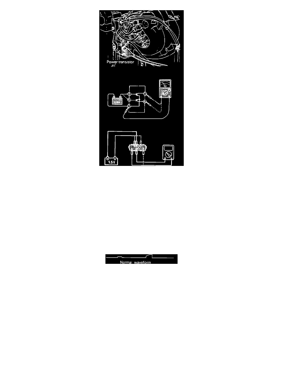
Disconnect the power transistor connector.
2.
Connect a power supply of 1.5v (one dry cell) between power transistor terminals 3 (-) and 2 (+).
3.
Check for continuity between terminals 1 (+) and 3 (-). There should be continuity.
4.
Remove power from terminals 3 and 2.
5.
Check for continuity between terminals 1 (+) and 3 (-). There should not be continuity.
6.
Connect a power supply of 1.5v (one dry cell) between power transistor terminals 3 (-) and 5 (+).
7.
Check for continuity between terminals 6 (+) and 3 (-). There should be continuity.
8.
Remove power from terminals 3 and 6.
9.
Check for continuity between terminals 6 (+) and 3 (-). There should not be continuity.
If the Power Transistor fails any of these tests, replace the Power Transistor.
OSCILLOSCOPE TEST
Power Transistor Control Signal Scope Pattern
Power transistor control signal test.
1. Run engine at idle speed.
2. Connect the scope probe to pick-up point #2 (one side at a time) shown in the System Schematic diagram and compare each signal to the pattern
shown.
Refer to COMPUTERIZED ENGINE CONTROLS for further information.