
Mirage L4-1597cc 1.6L SOHC Turbo (1985)
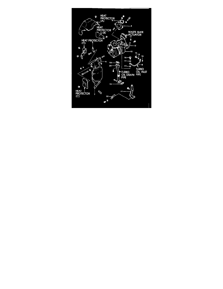
FIGURE 2
d)
Heat protectors A, D, and C (Fig. 2)
e)
Waste gate actuator (Fig. 2)
6.
Disconnect the turbo water hose from the water pipe.
7.
Remove the bolt securing the water pipe to its bracket.
8.
Disconnect and remove the turbo oil inlet and drain pipes. Inspect for restrictions; clean out if restricted.
9.
Disconnect the turbo coolant drain pipe eyebolt at the turbo.
10.
Remove the coupling bolt and coupling joining the two halves of the turbo charger.
11.
Carefully withdraw the compressor cover and cartridge from the turbine housing.
12.
Inspect the turbine housing. If worn or damaged, remove it by first disconnecting the catalytic converter and then disconnecting the turbine
housing from the exhaust manifold.
TURBO DISASSEMBLY ON THE BENCH
1.
Clamp the turbo in a soft jawed vise.
2.
Mark the compressor cover to simplify alignment of the cartridge and compressor cover during reassembly.
3.
Remove the water pipe (A) and fittings.
4.
Remove the snap ring and disassemble the turbo.
5.
Inspect all parts as described in STB-84-14-010. Replace any that are worn or damaged.
6.
Using a hand pressure pump, test the waste gate actuator for proper operation. The diaphragm should hold pressure, the rod should extend fully
and the hose and connections should not leak. If defective, replace the component.
BENCH ASSEMBLY
1.
Assemble the water pipe (A) to the cartridge using new gaskets MF660064. Leave the eyebolt loose.
2.
Lubricate the O-ring, and assemble the cartridge to the compressor cover in line with the mark made in Step 2 above. Align the water pipe 90~ to
the machined face of the compressor cover. Tighten the eyebolt to 12-15 N-m (9-11 ft.lbs.).
3.
Reinstall the snap ring, beveled side out.
REASSEMBLY ON THE VEHICLE
1.
If the turbine housing has been removed, reinstall the steel gaskets between the turbine housing and exhaust manifold and between the catalytic
converter and turbine housing (the tab on this gasket must be located), and reinstall the bolts and nut. Torque to 50-68 N-m (36-50 ft.lbs.).
2.
Carefully insert the compressor cover and turbo cartridge into the turbine housing.
3.
Reinstall the coupling, but leave the nut loose.
4.
Reconnect the coolant and oil pipes with new gaskets. Torque the eyebolt to 28-33 N-m (21-25 ft.lbs.), and torque the oil pipe bolts to 8-9.5 N-m
(6-7 ft.lbs.).
5.
Tighten the coupling nut to 10-11 N-m (7-8 ft.lbs.).
6.
Connect the coolant hose to the water pipe and reinstall the clamp and attaching screw.
7.
Reinstall the turbo waste gate actuator. Torque the attaching bolts to 8-12 N-m (6-9 ft.lbs.). Connect the hose.
8.
Reinstall heat protectors (A) and (D).
9.
Reinstall the secondary air tube assembly.