mitsubishi Workshop Repair Guides

Mitsubishi Workshop Service and Repair Manuals

Restraints - Revised Clockspring Alignment Procedure|Page 5140 > < Restraints - Revised Clockspring Alignment Procedure|Page 5138
Page 2
background image

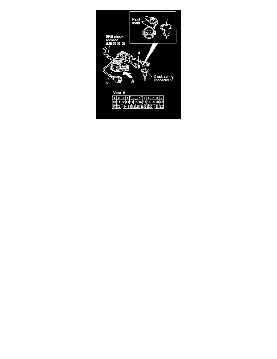
4. Align the paint mark of the SRS check harness connector No.4 with the notch in clock spring connector No.2 (arrow in the illustration) to connect

the connectors Nos.2 and 4.

5. Check continuity between the terminals 22 and 23 of the SRS check harness connector No.5.

Restraints - Revised Clockspring Alignment Procedure|Page 5140 > < Restraints - Revised Clockspring Alignment Procedure|Page 5138