
Mirage Sedan LS L4-1834cc 1.8L SOHC MFI (1999)
Clockspring Assembly / Spiral Cable: Adjustments
The content of this article reflects the changes identified in TSB-08-52B-001
CAUTION:
1. Never attempt to disassemble or repair the air bag module or clock spring. If faulty, replace it.
2. Do not drop the air bag module or clock spring or allow contact with water, grease or oil. Replace it if a dent, crack, deformation or rust are
detected.
3. The air bag modules should be stored on a flat surface and placed so that the pad surface is facing upward.
Do not place anything on top of the air bag modules.
4. Do not expose the air bag module to temperature over 93° C (200° F).
5. Once an air bag has deployed, be sure to replace the air bag module with a new one. Check the clock spring and replace if faulty.
6. Wear gloves and safety glasses when handling an air bag that has deployed.
7. An undeployed air bag module should only be disposed of in accordance with the disposal procedures.
A modified clock spring has been adopted for Service Parts on affected vehicles as of September 2007. New and old style parts are interchangeable. This
TSB advises the procedures for alignment of the neutral point of the new clock spring when a part is replaced.
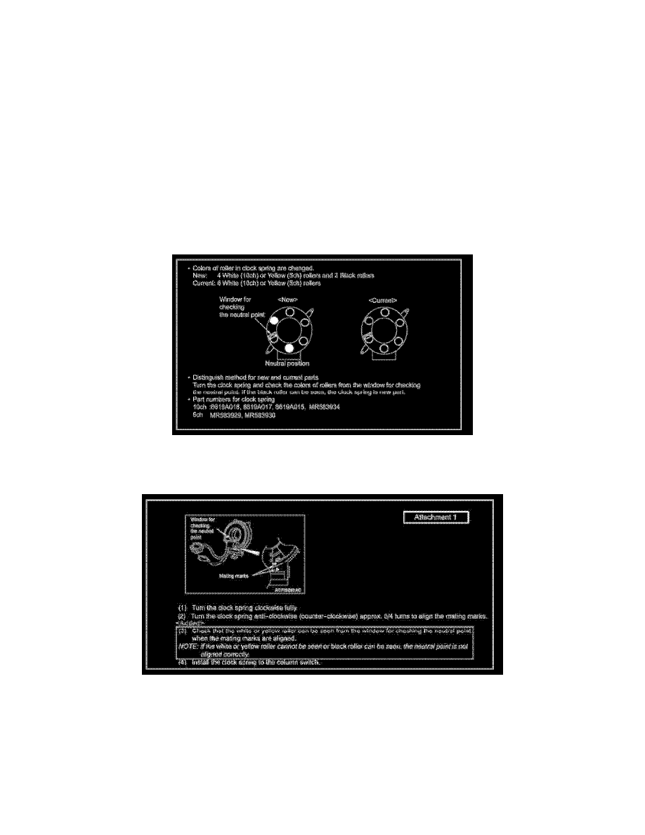
Parts Identification
Replacement Clockspring Alignment As Per Manual Update TSB-08-52B-001
Mating Mark Alignment
Replacement Clockspring Alignment As Per Manual Update TSB-08-52B-001 (Part 2)
1. Turn the clockspring clockwise fully.
2. Turn the clockspring anti-clockwise (counter-clockwise) approx. 3/4 turns to align the mating marks.
3. Check that the white or yellow roller can be seen from the window for checking the neutral point when the mating marks are aligned.
NOTE: If the white or yellow roller cannot be seen or black roller can be seen, the neutral point is not aligned correctly.
4. Install the clockspring to the column switch.