
Montero V6-3.8L SOHC (2005)
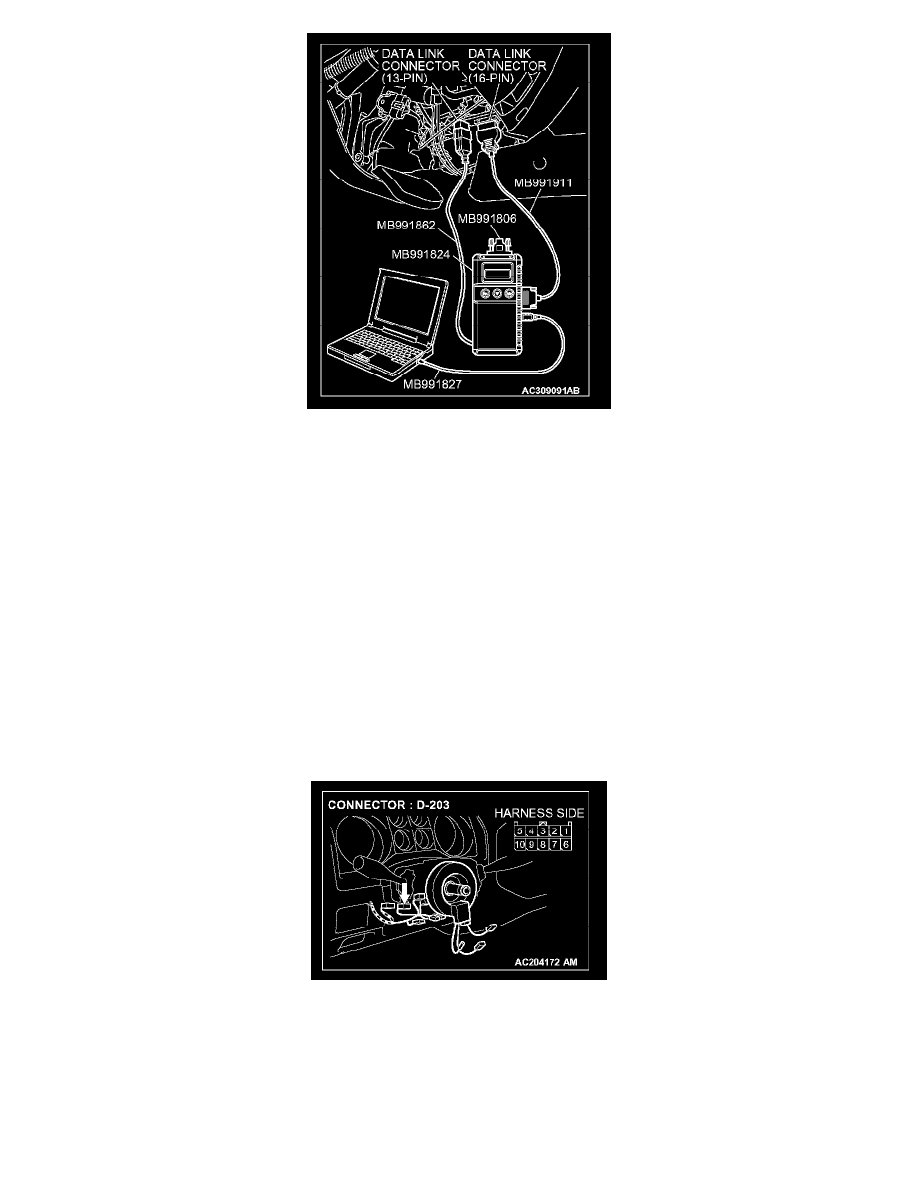
1. Connect the special tool. Refer to "How to connect SWS monitor". See: Reading and Clearing Diagnostic Trouble Codes/How to Connect SWS
Monitor
2. Turn the ignition switch to the "LOCK" (OFF) position.
3. Operate scan tool MB991958 according to the procedure below to display "ECU COMM CHK."
1. Select "SYSTEM SELECT."
2. Select "SWS."
3. Select "SWS MONITOR."
4. Select "ECU COMM CHK."
4. Scan tool MB991958 should show "OK" on the "ECU COMM CHK" menus for both the "ETACS ECU" and the "COLUMN ECU" menus.
Q: Is "OK" displayed on both the "ETACS ECU" and "COLUMN ECU" menus?
"OK" are displayed for all the items : Go to Step 2.
"NG" is displayed on the "COLUMN ECU" menu : Go to Step 2.
"NG" is displayed on the "ETACS ECU" menu : Refer to Inspection Procedure A-3 "Communication with ETACS-ECU is not possible."
"NG" are displayed for all the items : Refer to Inspection Procedure A-3 "Communication with ETACS-ECU is not possible."
STEP 2. Check column switch connector D-203 for loose, corroded or damaged terminals, or terminals pushed back in the connector.
Q: Is column switch connector D-203 in good condition?
YES: Go to Step 3.
NO: Repair or replace the damaged component(s). The system should communicate with the column switch (column-ECU) normally.
STEP 3. Check the battery power supply circuit to the column switch. Test at column switch connector D-203.