
Montero V6-3.8L SOHC (2005)
ETACS-ECU Power Supply And SWS Communication Circuit Part 2
CIRCUIT OPERATION
-
The power supply to the ETACS-ECU is provided by the battery and the ignition switch (IG1).
-
If the power supply system from the battery is defective, the system operates by the power supply from the ignition switch (IG1).
TECHNICAL DESCRIPTION (COMMENT)
It is suspected that the power supply circuit to the ETACS-ECU is defective, or the wiring harness between the SWS monitor kit and the ETACS-ECU or
their connector(s) is damaged. If the battery power supply circuit to the ECU (terminal 6 of the ETACS-ECU) is damaged, also check the power supply
circuit from the ignition switch (IG1) (terminal 16 of the ETACS-ECU), and repair if necessary. If the ground circuit to the ECU (terminal 20 of the
ETACS-ECU) is damaged, also check the ground circuit to the sensor (terminal 23 of the ETACS-ECU), and repair if necessary.
TROUBLESHOOTING HINTS
-
The ETACS-ECU may be defective
-
The wiring harness or connectors may have loose, corroded, or damaged terminals, or terminals pushed back in the connector
DIAGNOSIS
Required Special Tools:
-
MB991223: Harness Set
-
MB991958: Scan Tool (MUT-III Sub Assembly)
-
MB991824: Vehicle Communication Interface (V.C.I.)
-
MB991827: MUT-III USB Cable
-
MB991911: MUT-III Main Harness B
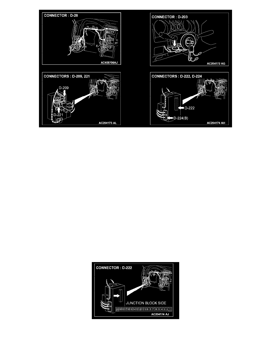
STEP 1. Check ETACS-ECU connector D-222 for loose, corroded or damaged terminals, or terminals pushed back in the connector.
Q: Is ETACS-ECU connector D-222 in good condition?