
Montero V6-3.8L SOHC (2005)
YES: Go to Step 2.
NO: Check the RV meter. Refer to RV meter.
STEP 2. Use scan tool MB991958 to select "ECU COMM CHK" on the SWS monitor display.
Check the following ECUs:
-
ETACS-ECU
-
RV meter
CAUTION: To prevent damage to scan tool MB991958, always turn the ignition switch to the "LOCK" (OFF) position before connecting or
disconnecting scan tool MB991958.
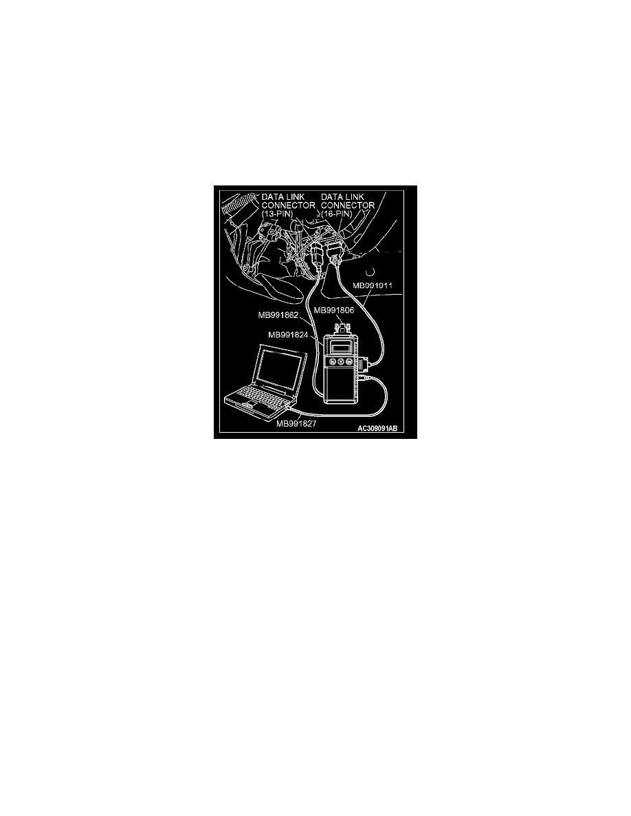
1. Connect the special tool. Refer to "How to connect SWS monitor". See: Reading and Clearing Diagnostic Trouble Codes/How to Connect SWS
Monitor
2. Connect SWS monitor kit MB991862 to the data link connector (13-pin).
3. Turn the ignition switch to the "LOCK" (OFF) position.
4. Operate scan tool MB991958 according to the procedure below to display "ECU COMM CHK."
1. Select "SYSTEM SELECT."
2. Select "SWS."
3. Select "SWS MONITOR."
4. Select "ECU COMM CHK."
5. Scan tool MB991958 should show "OK" on the "ECU COMM CHK" menus for both the "ETACS ECU" and the "CENTER DISP." menus.
Q: Is "OK" displayed on both the "ETACS ECU" and "CENTER DISP." menu?
"OK" are displayed for all the items : Go to Step 3.
"NG" is displayed on the "ETACS ECU" menu : Refer to Inspection Procedure A-3 "Communication with ETACS-ECU is not possible."
"NG" is displayed on the "CENTER DISP." menu : Refer to Inspection procedure A-6 "Communication with RV meter is not possible."
STEP 3. Check the input signal by using "FUNCTION DIAG." menu of the SWS monitor.
Turn the ignition switch to the "ON" position to check the input signals from the following switches.