
Montero V6-3.8L SOHC (2005)
STEP 19. Check the wiring harness between rear combination light (LH) connector G-02 (terminal 5) and ETACS-ECU connector D-222
(terminal 15).
NOTE: Also check junction block connector D-217 and intermediate connector D-125 for loose, corroded, or damaged terminals, or terminals pushed
back in the connector. If junction block connector D-217 or intermediate connector D-125 is damaged, repair or replace the damaged component(s) as
described in Harness Connector Inspection.
Q: Is the wiring harness between rear combination light (LH) connector G-02 (terminal 5) and ETACS-ECU connector D-222 (terminal 15) in good
condition?
YES: Replace the socket assembly. Verify that the turn-signal lights illuminate normally.
NO: The wiring harness may be damaged or the connector(s) may have loose, corroded or damaged terminals, or terminals pushed back in the
connector. Repair the wiring harness as necessary. Verify that the turn-signal lights illuminate normally.
STEP 20. Check the rear turn-signal light bulb (RH).
1. Remove the rear turn-signal (RH) light bulb.
2. Verify that the rear turn-signal light bulb (RH) is not damaged or burned out.
Q: Is the rear turn-signal (RH) light bulb in good condition?
YES: Go to Step 21.
NO: Replace the rear turn-signal (RH) light bulb. Verify that the turn-signal lights illuminate normally.
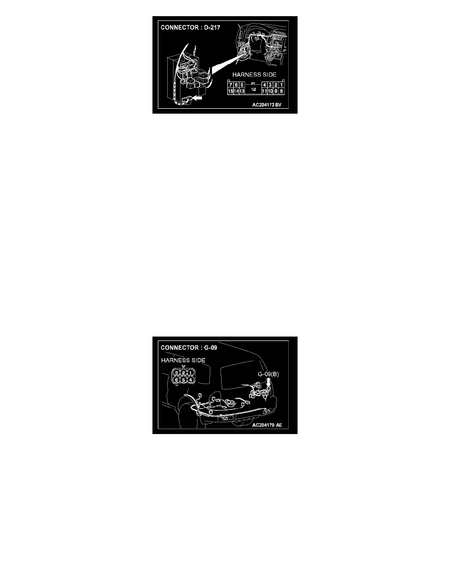
STEP 21. Check rear combination light (RH) connector G-09 for loose, corroded or damaged terminals, or terminals pushed back in the
connector.
Q: Is rear combination light (RH) connector G-09 in good condition?
YES: Go to Step 22.
NO: Repair or replace the damaged component(s). Refer to Harness Connector Inspection. Verify that the turn-signal lights illuminate normally.
STEP 22. Check the ground circuit to the rear combination light (RH). Test at rear combination light (RH) connector G-09.