
Montero V6-3.8L SOHC (2005)
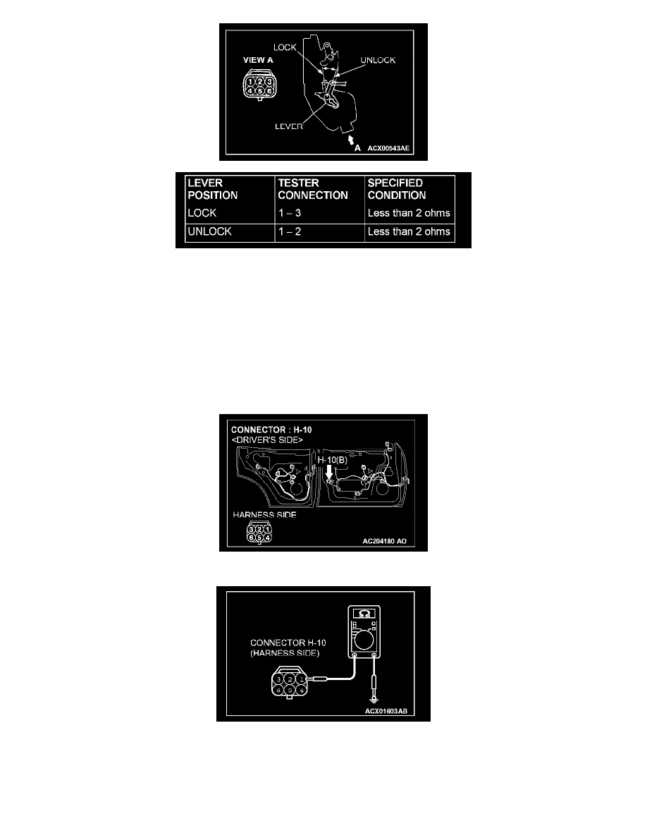
STEP 3. Check the driver's door lock actuator switch.
Disconnect driver's door lock actuator switch connector H-10. Then check continuity between the switch terminals.
Q: Is the driver's door lock actuator switch in good condition?
YES: Go to Step 4.
NO: Replace the driver's door lock actuator switch. If the functions, which are described in "CIRCUIT OPERATION", work normally, the input
signal from the driver's door lock actuator switch should be normal.
STEP 4. Check the ground circuit to the driver's door lock actuator switch. Test at driver's door lock actuator switch connector H-10.
1. Disconnect driver's door lock actuator switch connector H-10 and measure the resistance available at the wiring harness side of the connector.
2. Measure the resistance value between terminal 1 and ground.
-
The resistance should equal 2 ohms or less.
Q: Is the measured resistance 2 ohms or less?
YES: Go to Step 6.