
Montero V6-3.8L SOHC (2005)
"OK" are displayed for all the items : Go to Step 2.
"NG" is displayed on the "COLUMN ECU" menu : Refer to Inspection Procedure A-2 "Communication with column switch (column-ECU) is
not possible."
"NG" is displayed on the "FRONT ECU" menu : Refer to Inspection procedure A-4 "Communication with front-ECU is not possible."
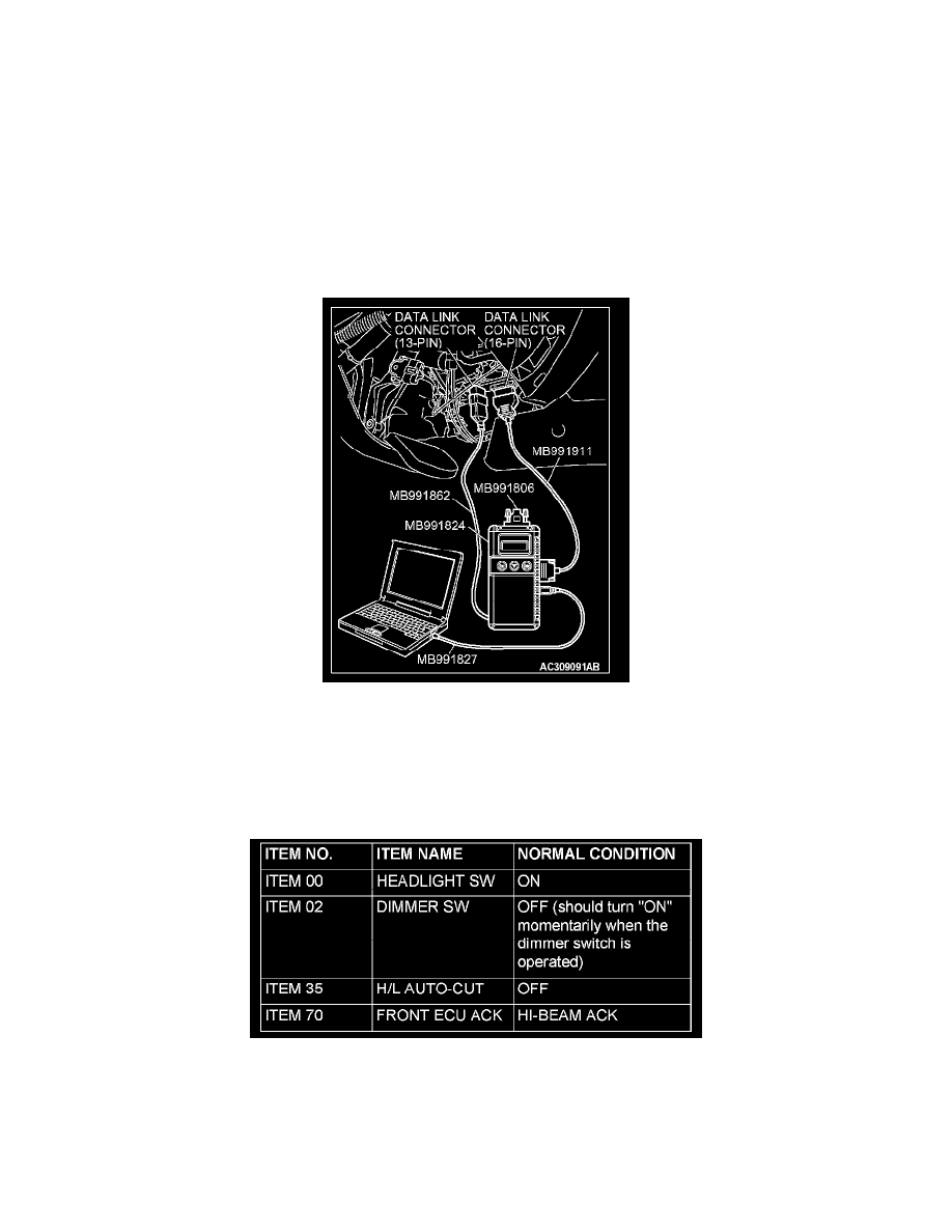
STEP 2. Check the input signal by using "FUNCTION DIAG." menu of the SWS monitor.
Check the input signals from the following switches:
-
Ignition switch: ON
-
Lighting switch: HEAD
-
Dimmer switch: ON
Operate scan tool MB991958 according to the procedure below to display "HEADLIGHT HI."
1. Select "SYSTEM SELECT."
2. Select "SWS."
3. Select "SWS MONITOR."
4. Select "FUNCTION DIAG."
5. Select "LIGHTING."
6. Select "HEADLIGHT HI."
Check that normal conditions are displayed on the items described in the given table.
Q: Are normal conditions displayed on the "HEADLIGHT SW", "DIMMER SW","H/L AUTO-CUT" and "FRONT ECU ACK"?
Normal conditions are displayed for all the items : Go to Step 3.
Normal condition is not displayed on the "HEADLIGHT SW" : Refer to Inspection Procedure O-6 "ETACS-ECU does not receive any signal