
Montero V6-3.8L SOHC (2005)
STEP 7. Check the wiring harness between taillight (LH) connector G-16 (terminal 1) and front-ECU connector A-07X (terminal 8).
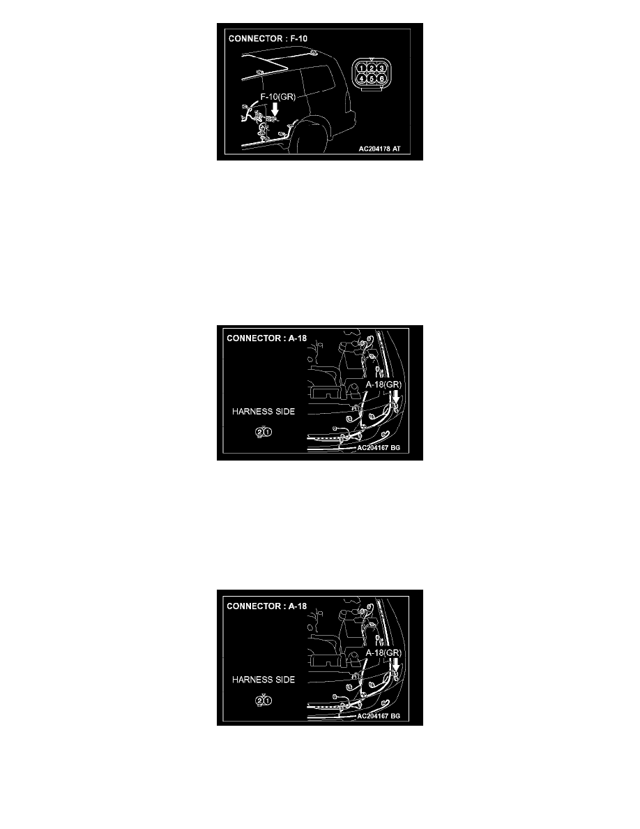
NOTE: Also check intermediate connectors D-28, D-111 and F-10 for loose, corroded, or damaged terminals, or terminals pushed back in the
connector. If intermediate connector D-28, D-111 or F-10 is damaged, repair or replace the damaged component(s) as described in Harness Connector
Inspection.
Q: Is the wiring harness between taillight (LH) connector G-16 (terminal 1) and front-ECU connector A-07X (terminal 8) in good condition?
YES: No action is necessary and testing is complete.
NO: The wiring harness may be damaged or the connector(s) may have loose, corroded or damaged terminals, or terminals pushed back in the
connector. Repair the wiring harness as necessary. Verify that the taillight (RH) and side marker light (RH) illuminates normally.
STEP 8. Check position light (LH) connector A-18 for loose, corroded or damaged terminals, or terminals pushed back in the connector.
Q: Is position light (LH) connector A-18 in good condition?
YES: Go to Step 9.
NO: Repair or replace the damaged component(s). Refer to Harness Connector Inspection. Verify that the position light illuminates normally.
STEP 9. Check the ground circuit to the position light (LH). Test at position light (LH) connector A-18.
1. Disconnect position light (LH) connector A-18 and measure the resistance available at the wiring harness side of the connector.