
Montero V6-3.8L SOHC (2005)
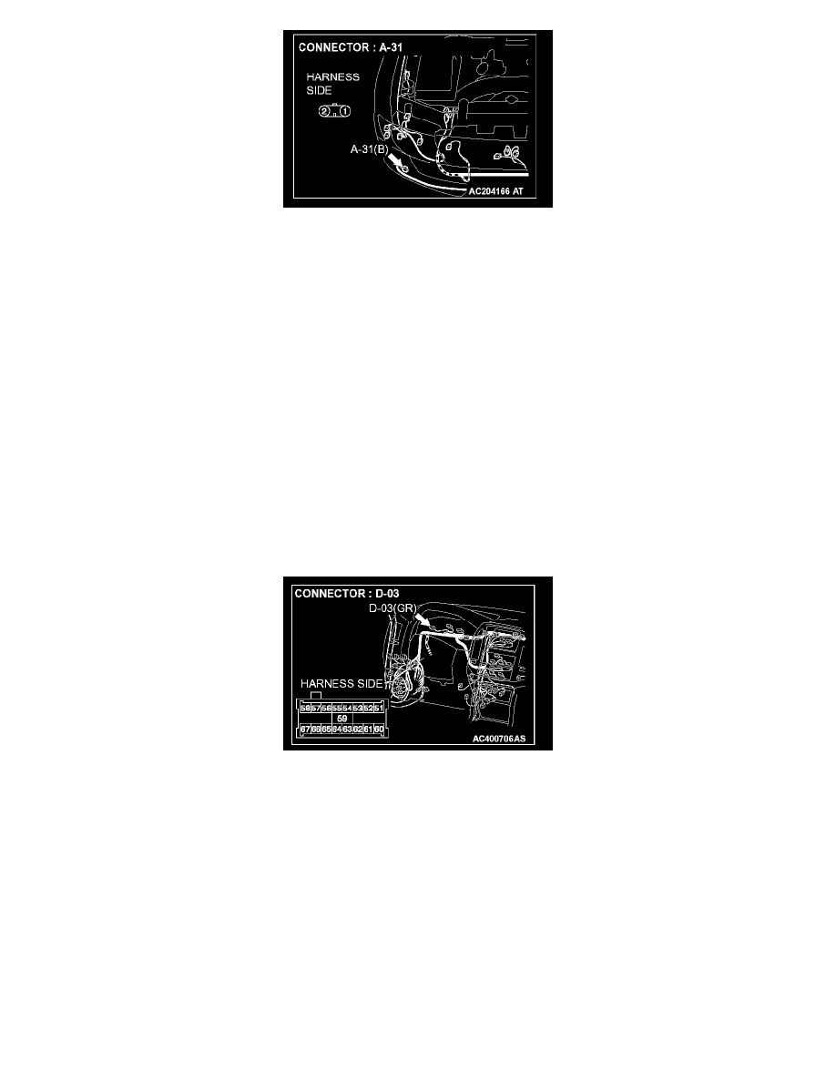
STEP 13. Check the wiring harness between joint connector (2) A-15 (terminal 2) and fog light (RH) connector A-31 (terminal 1).
NOTE: Also check intermediate connector A-25 for loose, corroded, or damaged terminals, or terminals pushed back in the connector. If intermediate
connector A-25 is damaged, repair or replace the damaged component(s) as described in Harness Connector Inspection.
Q: Is the wiring harness between joint connector (2) A-15 (terminal 2) and fog light (RH) connector A-31 (terminal 1) in good condition?
YES: No action is necessary and testing is complete.
NO: The wiring harness may be damaged or the connector(s) may have loose, corroded or damaged terminals, or terminals pushed back in the
connector. Repair the wiring harness as necessary. Verify that the fog lights illuminate normally.
STEP 14. Check the fog light indicator light bulb.
1. Remove the fog light indicator light bulb.
2. Verify that the fog light indicator light bulb is not damaged or burned out.
Q: Is the fog light indicator light bulb in good condition?
YES: Go to Step 15.
NO: Replace the fog light indicator light bulb. Verify that the fog light indicator light illuminates normally.
STEP 15. Check combination meter connector D-03 for loose, corroded or damaged terminals, or terminals pushed back in the connector.
Q: Is combination meter connector D-03 in good condition?
YES: Go to Step 16.
NO: Repair or replace the damaged component(s). Refer to Harness Connector Inspection. Verify that the fog light indicator light illuminates
normally.
STEP 16. Check the ground circuit to the fog light indicator light. Test at combination meter connector D-03.