
Montero 4WD V6-3.5L SOHC (1998)
NOTE:
For 1997 Montero Sport models, refer to the circuit diagram on page 90-71 in Volume 2 of the 1997 Montero Sport service manual. For 1998
Montero Sport models, refer to the circuit diagram on page 90-73 in Volume 2 of the 1998 Montero Sport service manual.
b.
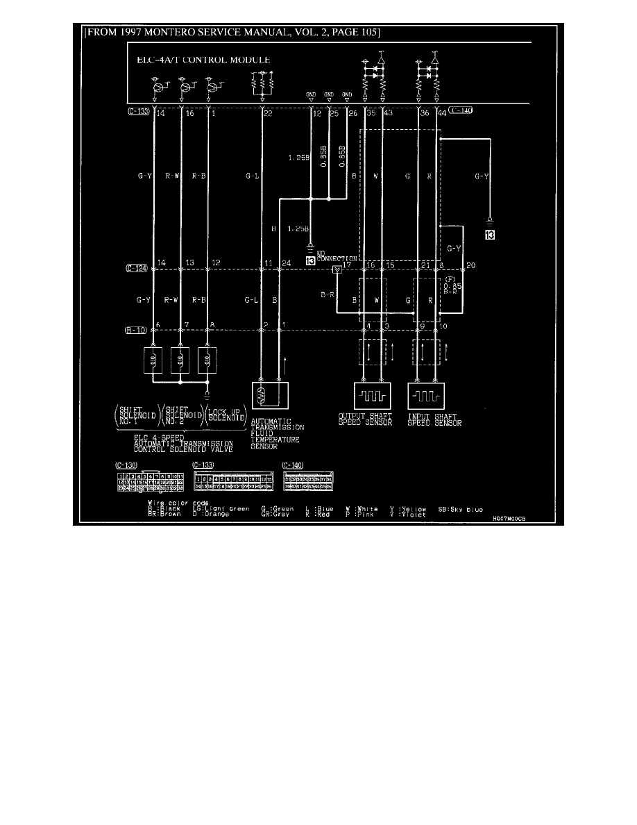
If the resistance reading in Step 3a was out of specification, check the resistance at the appropriate pulse generator. Resistance should be
560 - 680 ohms at 20° C (68°F).
NOTE:
A difference of 5 ohms or more in the resistance reading taken at the TCM connector and the reading taken at the sensor typically indicates that there
is a problem in a harness or connector.
(1)
If both pulse generators are within specification, check all associated harnesses for continuity. Repair or replace the harness and/or
connectors as necessary. Then go to Step 5.
(2)
If both pulse generators are within specification and abnormal readings for pulse generator "B" were found in Step 2, go to Step 4 for
sensor rotor inspection.
(3)
If pulse generator "A" is not within specification, replace it. Then go to Step 5.
(4)
If pulse generator "B" is not within specification, it must replaced and the sensor rotor must be inspected as described in Step 4.
4.
Remove pulse generator "B" and inspect the sensor rotor for looseness or damage through the mounting hole in the transmission case.