
Montero LS 4WD V6-2972cc 3.0L SOHC 12 Valve (1994)
5. Check for continuity between terminals 2 and 3.
Continuity: Should not exist
IGNITION COIL
1. Using an ohmmeter, check the resistance value between terminals 1 and 2.
Resistance value: 0.77 - 0.88 ohms
2. Using an ohmmeter, check the resistance value between terminals 2 and high tension terminal.
Resistance value: 11k - 13k ohms
If the Power Transistor / Ignition coil unit fails any of these tests, replace as a unit.
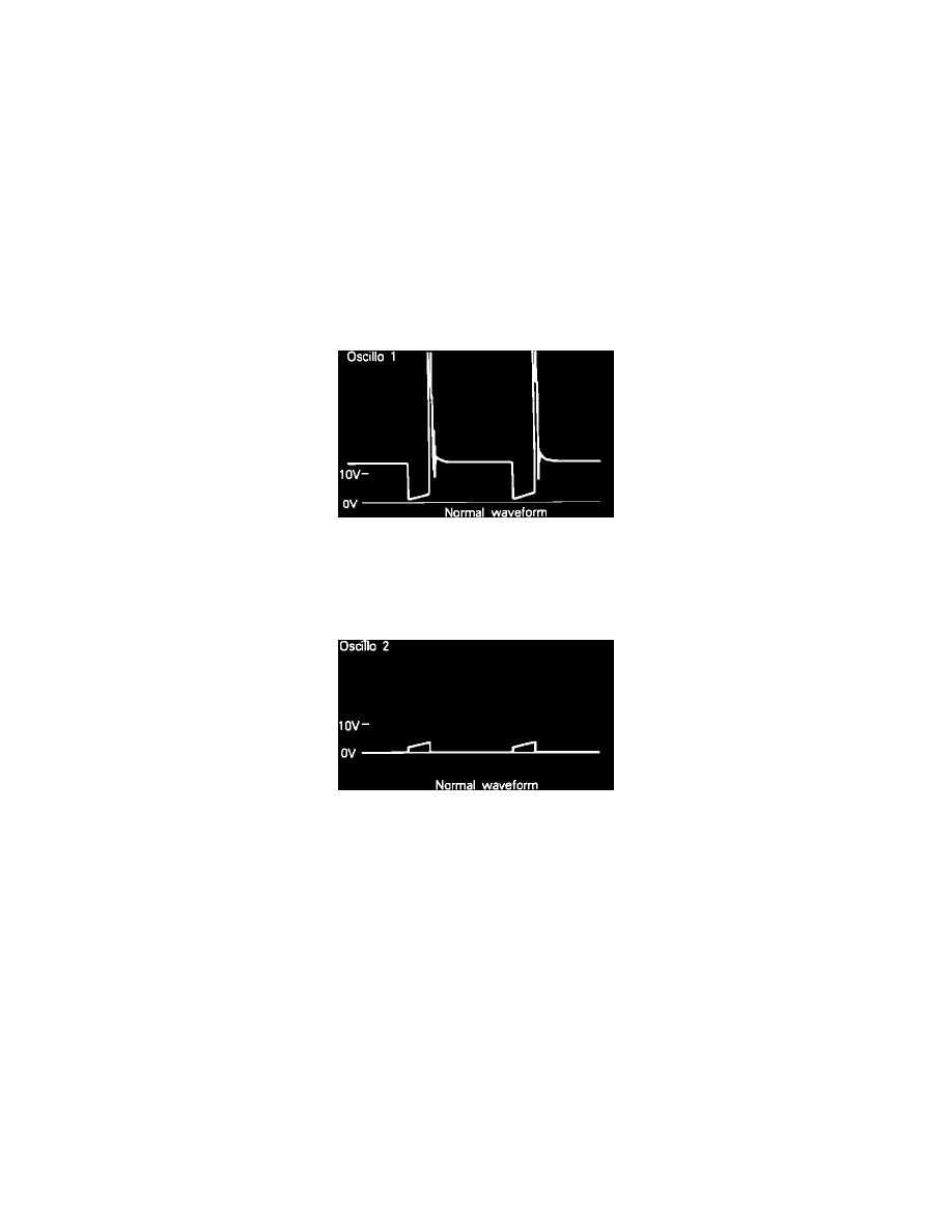
OSCILLOSCOPE TEST
1. Run engine at idle speed.
Primary Ignition Coil Signal Pattern
2. Connect the scope probe to pick-up point #1 shown in the system schematic diagram and compare the primary ignition coil signal to the pattern
shown.
3. Run engine at idle speed.
Power Transistor Control Signal Pattern
4. Connect the scope probe to pick-up point #2 shown in the system schematic diagram and compare the power transistor control signal to the pattern
shown.
If scope patterns are not as depicted in images, continue with the rest of the test procedures before replacing the assembly.
HARNESS TEST
1. Disconnect the ignition coil connector and turn the key to the ON position.
2. Using a voltmeter, check the voltage between ignition coil harness terminal 2 and ground.
Voltage: System voltage
3. Turn the key to the OFF position.
4. Disconnect the power transistor connector.
5. Using an ohm meter, check for continuity between ignition coil harness terminal 1 and the power transistor harness connector terminal 3.
Continuity: Should exist
6. Using an ohm meter, check for continuity between the power transistor harness connector terminal 2 and ground.
Continuity: Should exist