
Montero LS 4WD V6-2972cc 3.0L SOHC 12 Valve (1994)
Crankshaft Position Sensor: Testing and Inspection
NOTE: Proper testing of the Crankshaft Position Sensor involves testing the Camshaft Position Sensor also.
WAVE PATTERN INSPECTION WITH ANALYZER
1. Disconnect the connector of the camshaft position sensor, and connect the special tool (test harness: MB991348) across the disconnected
connector parts. (Connect the tool to all terminals.)
2. Connect the special patterns pickup of the analyzer to the terminal (1) of the distributor connector (in order to inspect the signal waveform of the
camshaft position sensor).
3. Connect the special patterns pickup of the analyzer to the terminal (2) of the crankshaft position sensor connector (in order to inspect the signal
waveform of the crankshaft position sensor).
Alternative Connection Method (when Special Harness is not available)
1. Connect the analyzer special patterns pickup to ECM terminal (68) for the camshaft position sensor.
2. Connect the analyzer special patterns pickup to ECM terminal (69) for the crankshaft position sensor.
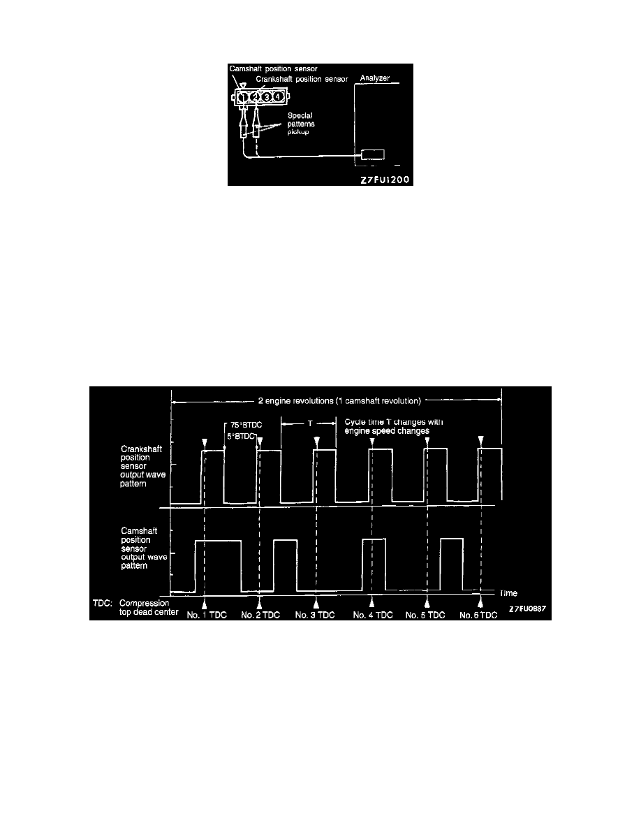
STANDARD WAVE PATTERN
Observation conditions set to the following:
Function: Special patterns
Pattern height: Low
Pattern selector: Display
Engine rpm: Idling (700 rpm)
Wave pattern observation points
Check that cycle time "T" becomes shorter and the frequency increases when the engine speed is increased.
EXAMPLES OF ABNORMAL WAVE PATTERNS