
Montero LS 4WD V6-2972cc 3.0L SOHC 12 Valve (1994)
ECM Connector Pin Numbers (from Wire Side)
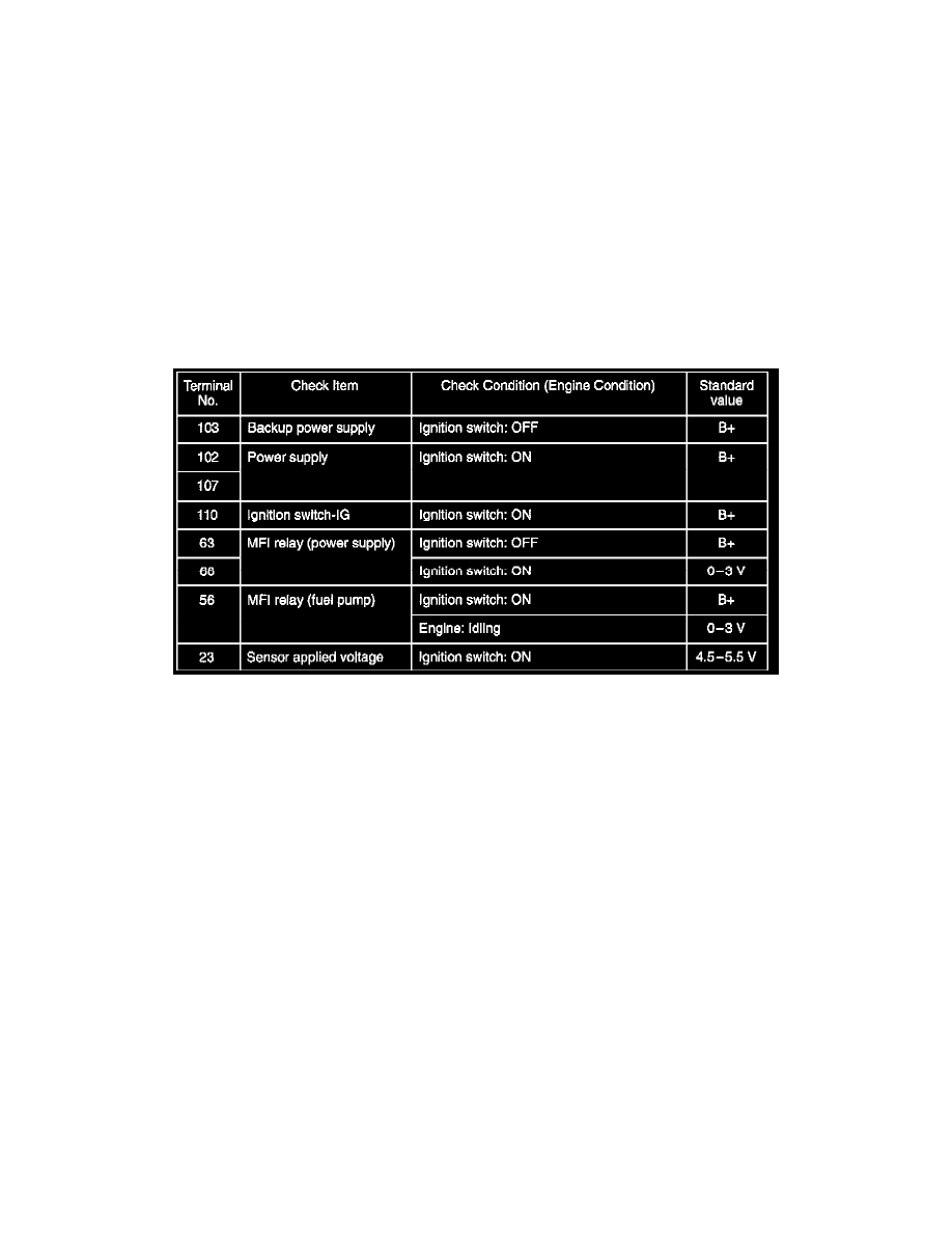
1. Connector a needle wire probe (test harness: MB991223 or paper clip) to a voltmeter probe.
2. Insert the needle wire probe into each of the engine control module connector terminals from the wire side, and measure the voltage while
referring to the check chart.
NOTES:
-
Make the voltage measurement with the engine control module connectors connected.
-
Make the voltage measurement between terminal (26) (ground terminal) and each terminal.
-
Pull out the engine control module to make it easier to reach the connector terminals.
-
The checks do not have to be carried out in the order given in the chart.
Caution: Never short-circuit the positive (+) probe between a connector terminal and ground, or the vehicle wiring, the sensor, the engine control
module, etc., will be damaged.
3. If the voltmeter indication is outside the standard value, check the corresponding sensor, actuator and related electrical wiring and repair or replace
as necessary.
4. After repairing or replacement, recheck with the voltmeter to confirm that the repair has corrected the problem.