
Montero LS 4WD V6-2972cc 3.0L SOHC 12 Valve (1994)
Torsion Bar: Service and Repair
1. Remove torsion bar locknut.
2. Measure distance "A" from end of anchor bolt to outer edge of nut, then remove torsion bar adjusting nut. If torsion bar is to be reused, when
reinstalling nut ensure distance "A" equals the value found prior to removal of nut.
3. Remove seat-holding nut, anchor bolt and nuts.
4. Remove torsion bar assembly.
5. Move the dust covers of the front and rear anchor arms and make mating marks on the anchor arms and the torsion bar. Remove the anchor arms
from the torsion bar.
6. Reverse procedure to install, noting the following:
a. When installing torsion bar, note that the marked end of the bar is to be installed toward the rear of the vehicle.
b. Apply suitable grease to the torsion bar serrations and dust covers.
c. If torsion bar is to be reused, reinstall anchor arms, ensuring they line up with mating marks.
d. Apply suitable grease to threaded part of anchor bolt.
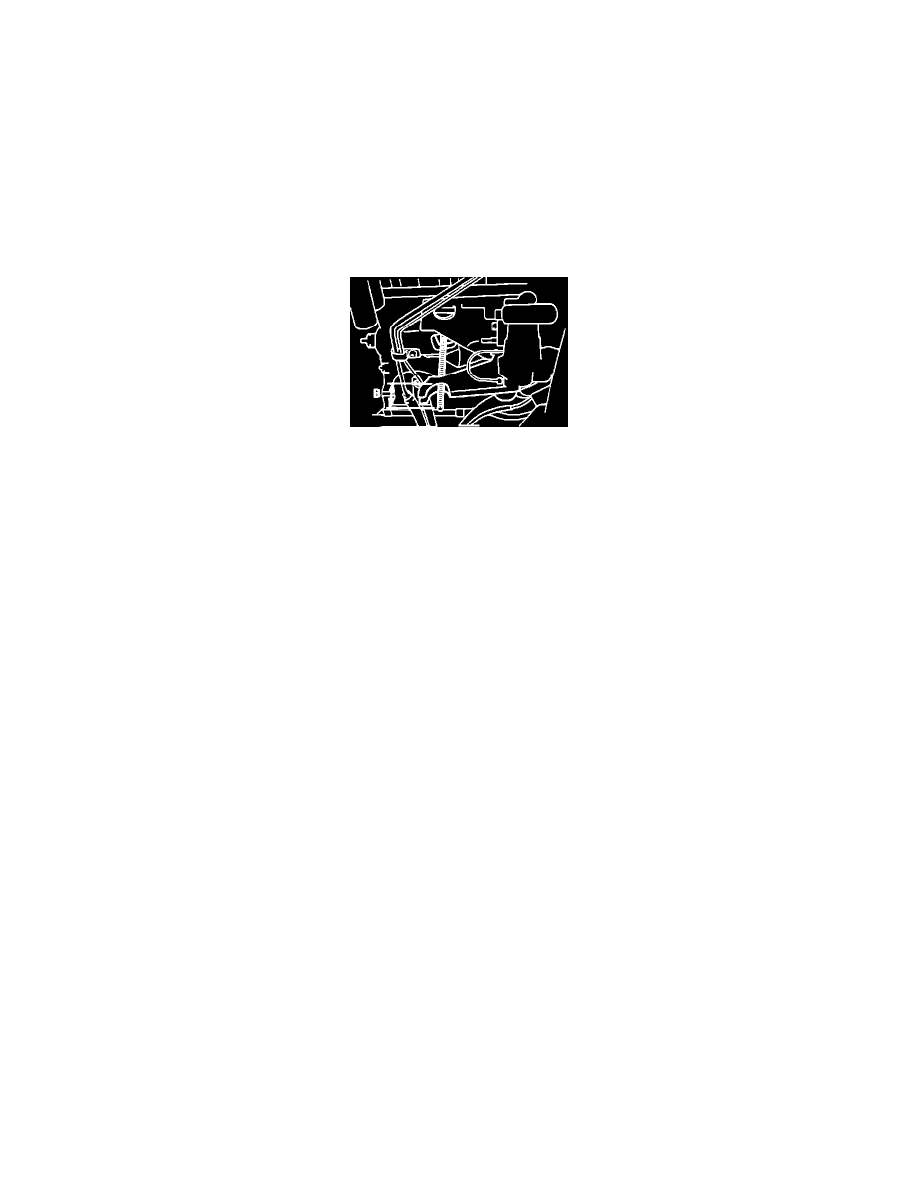
Fig. 18 Length Of Projection Of Anchor Bolt From Rear Anchor Arm
e. When using a new torsion bar, perform the following prior to installing torsion bar adjusting nut. Offset the torsion bar's and rear anchor arm's
phase so value of projection "B", Fig. 14, of the anchor bolt (from the rear anchor arm) is 1.42 inches. As a temporary adjustment of vehicle
height, tighten torsion bar adjusting nut until amount of projection of anchor bolt is 2.48 inches.