
Montero LS 4WD V6-2972cc 3.0L SOHC 24 Valve (1996)
ABS Braking Signal: Testing and Inspection
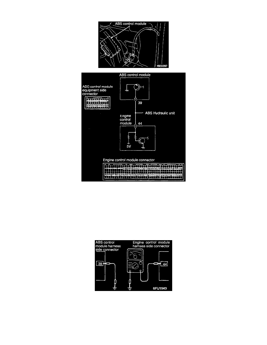
ANTI-LOCK BRAKING SIGNAL
OPERATION
-
The anti-lock braking signal is output by the Anti-lock Braking System (ABS) control module to the engine control module as a signal to
indicate whether the motor relay is being driven or not. The engine control module controls the idle air control motor by means of this signal,
and gives accurate anti-lock braking effectiveness.
-
The ABS control module turns the ignition power transistor ON when the motor relay is being driven, and the output terminal which has
battery positive voltage applied is short-circuited to the ground. This causes the anti-lock braking signal to change from HIGH to LOW.
HARNESS INSPECTION
STEP 1. Check for an open or short-circuit between the ABS control module and the engine control module.
-
ABS control module connector: Disconnected
-
Engine control module connector: Disconnected
OK: STOP
NG: Repair the harness. (39 - 44)