
Montero LS 4WD V6-2972cc 3.0L SOHC 24 Valve (1996)
CRANKSHAFT POSITION SENSOR
OPERATION
-
The crankshaft position sensor functions to detect the crank angle (position) of each cylinder, and to convert those data to pulse signals, which
are then input to the engine control module. The engine control module, based upon those signals, calculates the engine rpm, and also regulates
the fuel injection timing and the ignition timing.
-
The power for the crankshaft position sensor is supplied from the MFI relay and is grounded to the vehicle body. The crankshaft position
sensor, by intermitting the flow (to ground) of the 5 V voltage applied from the engine control module, produces pulse signals.
TROUBLESHOOTING HINTS
Hint 1:
If an impact is suddenly felt during driving or the engine suddenly stalls during idling, try shaking the crankshaft position sensor during idling. If
the engine stalls, the cause is probably improper or incomplete contact of the crankshaft position sensor's connector.
Hint 2:
If the crankshaft position sensor output r/min is 0 r/min during cranking when the engine cannot be started, the cause is probably a malfunction of
the crankshaft position sensor or a broken timing belt.
Hint 3:
If the indicated value of the crankshaft position sensor output r/min is 0 r/min during cranking when the engine cannot be started, the cause is
probably a failure of the ignition coil's primary current to intermittently pulse correctly, so a malfunction of the ignition system circuitry, the
ignition coil and/or the power transistor is the probable cause.
Hint 4:
If idling is possible even though the crankshaft position sensor indicated r/min is outside the standard value, the cause is usually a malfunction of
something other than the crankshaft position sensor.
Examples:
1. Malfunction of engine coolant-temperature sensor
2. Malfunction of idle air control motor
3. Incorrect adjustment of the standard idling speed.
INSPECTION
Wave Pattern Inspection using an Analyzer Measurement method
1. Disconnect the connector of the camshaft position sensor, and connect the special tool (test harness: MB991348) across the disconnected
connector parts. (Connect the tool to all terminals.)
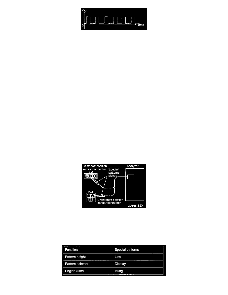
2. Connect the special patterns pickup of the analyzer to the terminal (2) of the camshaft position sensor connector.
3. Disconnect the connector of the crankshaft position sensor, and connect the special tool (test harness: MD998478) across the disconnected
connector parts.
4. Connect the special patterns pickup of the analyzer to the terminal (2) of the crankshaft position sensor connector.