
Montero LS 4WD V6-2972cc 3.0L SOHC 24 Valve (1996)
engine control module. The engine control module, based upon those signals, regulates the idle air control motor, etc.
-
The vehicle speed sensor, by intermitting by the lead switch the flow (to ground) of the approximately 5 V voltage applied from the engine
control module, produces vehicle speed signals.
TROUBLESHOOTING HINTS
If there is damaged or disconnected wiring or a short-circuit in the vehicle speed sensor signal circuit, the engine may stall when the vehicle speed
is reduced and the vehicle is stopped.
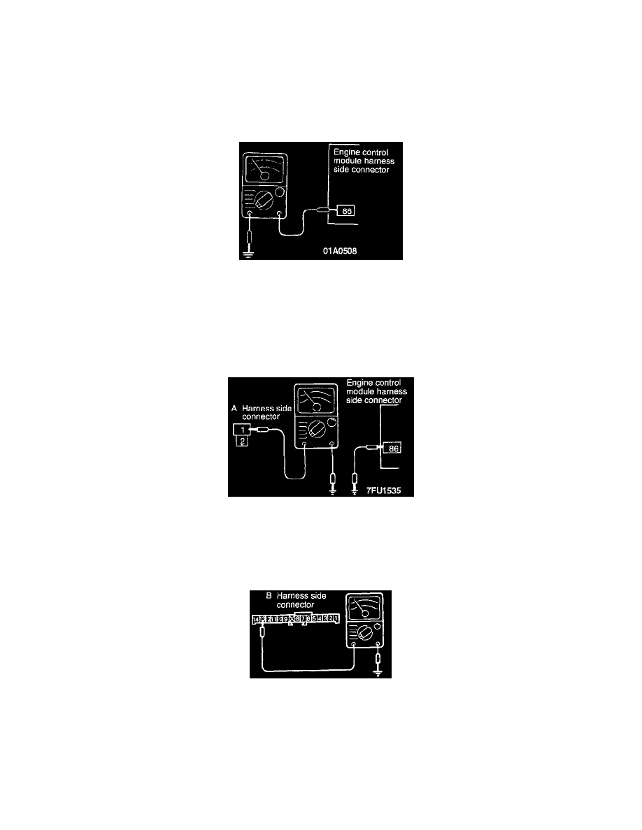
HARNESS INSPECTION
STEP 1. Check for continuity in the vehicle speed sensor output circuit.
-
Engine control module connector: Disconnected
-
Move the vehicle.
Continuity: Continuity and no-continuity are repeated alternately.
OK: GO TO STEP 4
NG: GO TO STEP 2
STEP 2. Check for an open or short-circuit between the vehicle speed sensor and the engine control module.
-
Engine control module connector: Disconnected
-
Vehicle speed sensor connector: Disconnected
OK: GO TO STEP 3
NG: Repair the harness. (A1 - 86)
STEP 3. Check for continuity in the ground circuit.
-
Vehicle speed sensor connector: Disconnected
OK: GO TO STEP 4
NG: Repair the harness. (B13 - Ground)