
Montero LS 4WD V6-2972cc 3.0L SOHC 24 Valve (1996)
INSPECTION
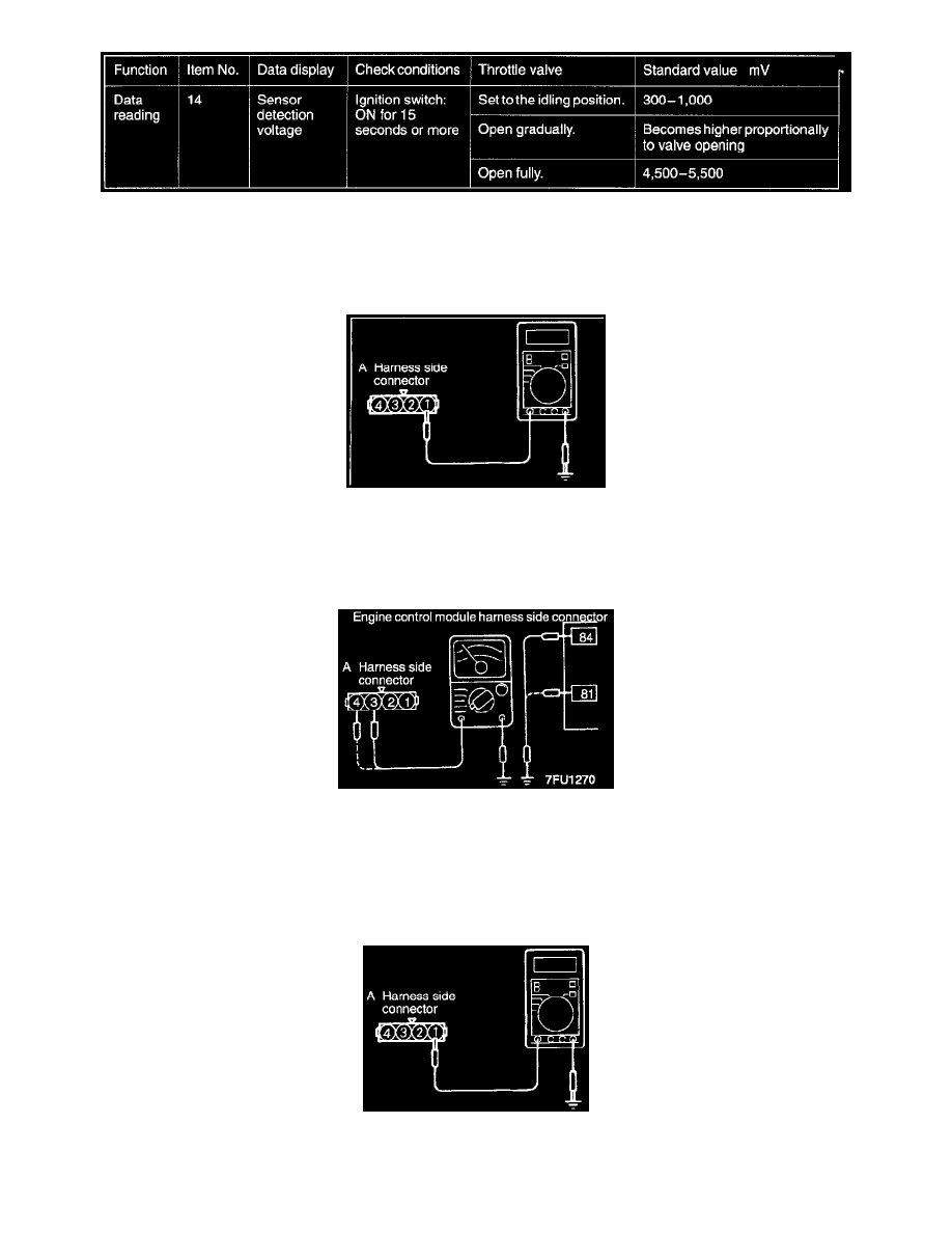
Using Scan Tool
HARNESS INSPECTION
STEP 1. Check for continuity in the ground circuit.
-
Throttle position sensor connector: Disconnected
OK: GO TO STEP 2
NG: Repair the harnesses. (A1 - 92)
STEP 2. Check for an open or short-circuit between the throttle position sensor and the engine control module.
-
Throttle position sensor connector: Disconnected
-
Engine control module connector: Disconnected
-
All control module connectors, such as the ECM connector, which use throttle position sensor output: Disconnected
OK: GO TO STEP 3
NG: Repair the harnesses. (A3 - 84, A4 - 81)
STEP 3. Measure the applied voltage.
-
Throttle position sensor connector: Disconnected
-
Engine control module connector: Connected