
Montero LTD 4WD V6-3.5L SOHC (2002)
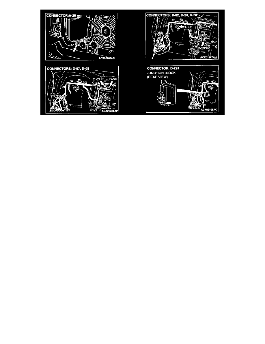
Connectors
CIRCUIT OPERATION
The RV meter calculates the ambient temperature using the ambient temperature sensor fitted on the vehicle side.
TECHNICAL DESCRIPTION (COMMENT)
When other indications are normal, the malfunction of ambient temperature sensor is considered.
TROUBLESHOOTING HINTS
-
Malfunction of the ambient temperature sensor
-
Damaged harness wires and connectors
DIAGNOSIS
Required Special Tools:
-
MB991223: Harness Set
-
MB991502: Scan Tool (MUT-II)
STEP 1. Check the communication and connection (M-BUS) of the service function.
1. Press the adjusting switch with the ignition switch at the "LOCK" (OFF) position. While holding the switch on the pressed condition, turn the
ignition switch to "ACC" position.
2. When the adjusting switch is continuously pressed for more than five seconds, the service function is activated at the same time with the reception
signal sound (pip sound) and the service mode screen is displayed.
3. Check the communication and connection.
Q: Isn't there any abnormality on the M-BUS?
YES: Go to Step 2.
NO: Go to Step 3.
Step 2. Check the communication and connection of the service function (SWS).
Q: Isn't there any abnormality on SWS?
YES: the RV meter display should operate normally.
NO: Refer to SWS Diagnosis-Symptom Chart.
STEP 3. Check the A/C-ECU