
Montero Sport V6-3.5L SOHC (2004)
5. Perform a tracing for 5 minutes or more with the engine speed of 4,500 r/min.
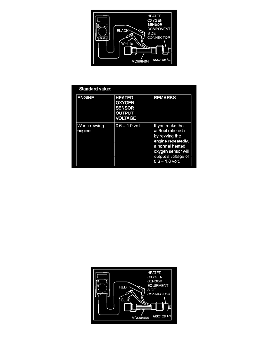
6. Connect a digital voltage meter between terminal No. 2 (black clip of special tool) and terminal No. 4 (white clip of special tool).
Standard Value:
2. While repeatedly revving the engine, measure the heated oxygen sensor output voltage.
CAUTION:
-
Be very careful when connecting the jumper wire; incorrect connection can damage the oxygen sensor.
-
Be careful the heater is broken when voltage of beyond 8 volts is applied to the oxygen sensor heater.
NOTE: If the sufficiently high temperature (of approximate 400 °C or more) is not reached although the oxygen sensor is normal, the output
voltage would be possibly low although the rich air-fuel ratio. Therefore, if the output voltage is low, use a jumper wire to connect the terminal
No.1 (red clip of special tool) and the terminal No. 3 (blue clip of special tool) of the oxygen sensor with a (+) terminal and (-) terminal of 8 volts
power supply respectively, then check again.
3. If the sensor is defective, replace the heated oxygen sensor.
NOTE: For removal and installation of the heated oxygen sensor, refer to Exhaust Pipe and Main Muffler.
<Left bank heated oxygen sensor (rear)>
1. Using scan tool MB991958, observe HO2S reading. If values are unsatisfactory, or if a scan tool is not available, use the following procedure: