
Montero Sport V6-3.5L SOHC (2004)
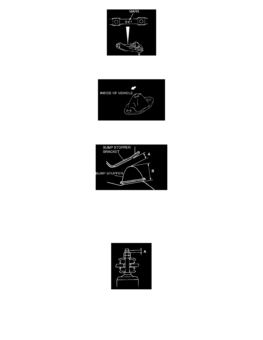
Install the upper arm so that the "OUT" mark on the upper arm shaft is facing toward the outside of the vehicle.
>>B<< REBOUND STOPPER INSTALLATION
Install the rebound stopper so that its arrow faces inside of the vehicle.
>>C<< BUMP STOPPER AND BUMP STOPPER BRACKET CLEARANCE ADJUSTMENT
1. With the vehicle in an unladen condition, dimension A from the bump stopper to the bump stopper bracket should be 18 - 20 mm (0.71 - 0.79
inch).
NOTE: Dimension A will be 18 mm (0. 71 inch) (B = 50 mm [2.0 inches]) when the bump stopper is a new part. When the bump stopper is
worn and becomes less than 50 mm (2.0 inches), dimension A will increase by the decreased amount.
2. If dimension A is not 18 - 20 mm (0.71 - 0.79 inch), adjust the rear anchor arm adjusting nut.
>>D<< SHOCK ABSORBER INSTALLATION
Install the shock absorber so that the distance (A) shown in the illustration is at the standard value.
Standard value (A): 1 - 2 mm (0.04 - 0.08 inch)
INSPECTION
UPPER ARM BALL JOINT BREAKAWAY TORQUE CHECK