
Montero Sport V6-3.5L SOHC (2004)
Transmission Position Switch/Sensor: Adjustments
TRANSMISSION RANGE SWITCH AND CONTROL CABLE ADJUSTMENT
Required Special Tool:
^
MB991958: Scan Tool (MUT-III Sub Assembly)
^
MB991824: V.C.I.
^
MB991827: MUT-III USB Cable
^
MB991911: MUT-III Main Harness B
1. Set the selector lever to the "N" position.
2. Loosen the control cable to manual control lever coupling nut to free the cable and lever.
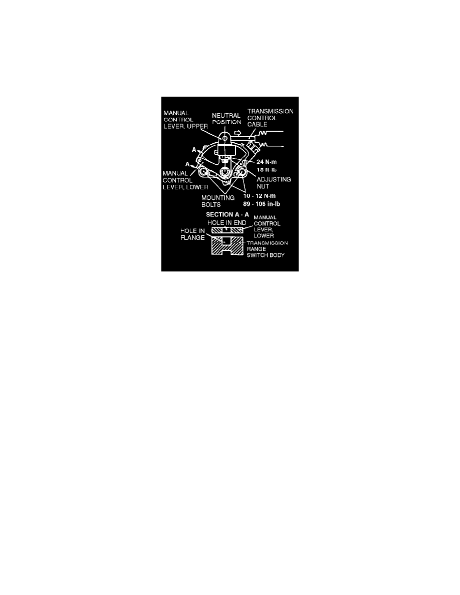
3. Set the manual control lever to the neutral position.
4. Loosen the transmission range switch body mounting bolts and turn the transmission range switch body so the hole in the end of the manual
control lever and the hole (cross section A - A in the figure on the left) in the flange of the transmission range switch body flange are aligned.
NOTE: The transmission range switch body can be aligned by inserting a 5-mm diameter steel bar into the end hole of the manual control lever
and the flange hole of the transmission range switch body.
5. Tighten the transmission range switch body mounting bolts to the specified torque. Be careful at this time that the switch body does not move.
Tightening torque: 10 - 12 Nm (89 - 106 inch lbs.)
6. Gently pull the transmission control cable in the direction of the arrow, until the cable is taut. Tighten the adjusting nut.
Tightening torque: 24 Nm (18 ft. lbs.)
7. Check that the selector lever is in the "N" position.
8. Check that each position of the manual control lever matches each position of the selector lever using scan tool MB991958.