
Montero Sport ES 2WD L4-2.4L SOHC (1999)
1. Connect scan tool MB991502 to the data link connector.
2. Check that the tone alarm of the scan tool MB991502 sounds when the ignition key is moved from the "LOCK" position to the "ON" position.
If the tone alarm of the scan tool MB991502 does not sound, there may be a malfunction in the input signal from the driver's side door switch. Go
to Step 2.
If the tone alarm of the scan tool MB991502 sounds when the driver's side door is opened [front door switch (LH) is turned to ON], the input
signal from the driver's side door switch to the scan tool MB991502 is normal. Replace the ETACS-ECU. Check that the malfunction is
eliminated.
<Vehicles with tone alarm-ECU>
Go to Step 2.
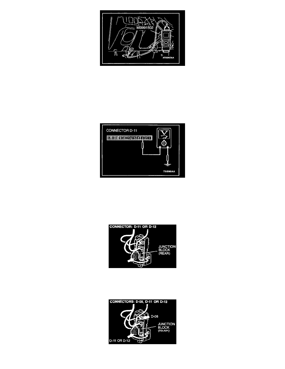
STEP 2. Check the input signal from the driver's side door switch.
1. Disconnect the ETACS-ECU connector D-11 or tone alarm-ECU connector D-12 and measure at the junction block side.
2. Turn the ignition switch "ON."
3. Measure the voltage between terminal number 3 and ground.
Voltage should be approximately 12 volts (battery positive voltage)
If approximately 12 volts, replace the ETACS-ECU or tone alarm-ECU. Check that the malfunction is eliminated.
If not approximately 12 volts, go to Step 3.
STEP 3. Check the ETACS-ECU connector D-11 or tone alarm-ECU connector D-12 for damage.
If harness connector D-11 or D-12 is damaged, repair or replace it.
If harness connector D-11 or D-12 is in good condition, go to Step 4.
STEP 4. Check the harness wires between the ignition switch (IG1) and ETACS-ECU connector D-11 or tone alarm-ECU D-12.