
Montero Sport LS 2WD V6-3.0L SOHC (1998)
Electronic Brake Control Module: Testing and Inspection
Diagnosis
32. ANTI-LOCK BRAKE SIGNAL SYSTEM
TROUBLESHOOTING HINTS
The most likely causes for this case:
-
Improper connector contact, open circuit or short-circuited harness wire.
-
Malfunction of the ABS-ECU.
-
Malfunction of the ECM.
DIAGNOSIS
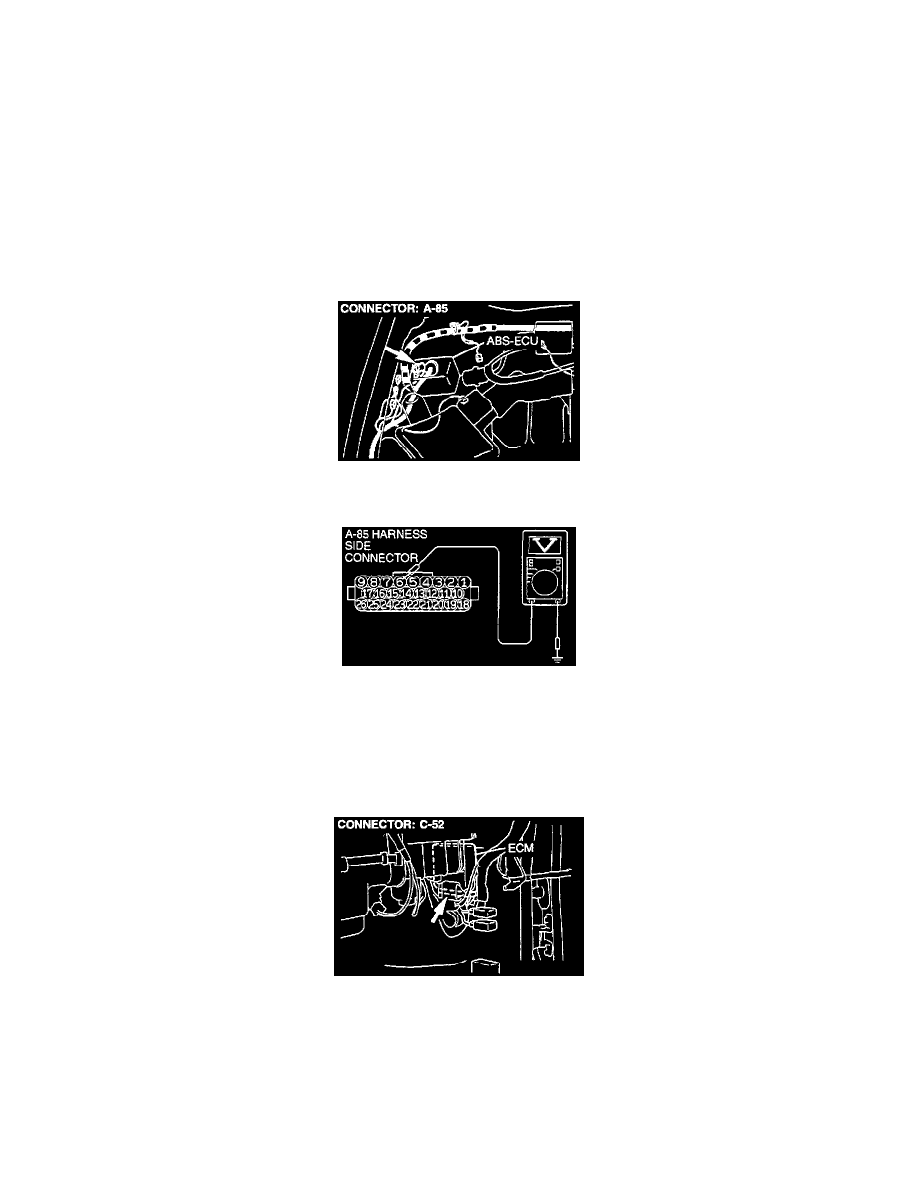
STEP 1. Check the circuit at the ABS-ECU connector A-85.
(1) Disconnect connector A-85 and measure at the harness side.
(2) Turn the ignition switch "ON."
(3) Measure the voltage between terminal 6 and ground.
-
Voltage should be approximately 12 volts (battery positive voltage).
(4) Turn the ignition switch "OFF."
-
If not within specification, go to Step 2.
-
If within specifications, go to Step 4.
STEP 2. Check the harness wire between the ECM connector C-52 and the ABS connector A-85.
-
If the wire between the ECM connector C-52 and the ABS connector A-85 is not damaged, go to Step 3.