
Montero Sport LS 2WD V6-3.0L SOHC (1998)
Throttle Position Sensor: Adjustments
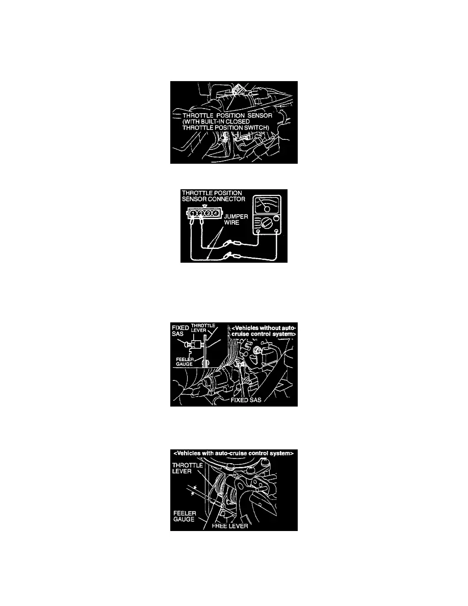
CLOSED THROTTLE POSITION SWITCH AND THROTTLE POSITION SENSOR ADJUSTMENT
Required Special Tools: MB991502 Scan Tool and MB991348 Test Harness Set
1. Connect the scan tool to the data link connector. When not using scan tool MB991502 proceed as follows.
(1) Disconnect the connector of the throttle position sensor.
(2) Connect an ohmmeter between terminals 2 (closed throttle position switch) and 1 (sensor ground) by using jumper wires.
2. Insert a feeler gauge as follows:
Vehicles without auto-cruise control system:
Insert a feeler gage with a thickness of 0.65 mm (0.026 inch) between the fixed SAS and the throttle lever.
Vehicles with auto-cruise control system:
Insert a feeler gauge with a thickness of 1.4 mm (0.055 inch) between the levers shown in the figure.
NOTE: Do not insert the feeler gauge 3 mm (0.118 inch) or more. If doing that, the throttle lever opening angle becomes larger than the
predetermined angle, causing maladjustment.