
Montero Sport LS 2WD V6-3.0L SOHC (1998)
WARNING: Support special tool MB991113 or MB990635 with a cord, etc. to prevent it tram coming off.
Use special tools MB991113 or MB990635 to disconnect the lower arm ball joint from the knuckle.
NOTE: Only loosen the tie rod end mounting nut, do not remove it from the ball joint.
INSTALLATION
Installation in reverse order as removal.
Installation Service Points
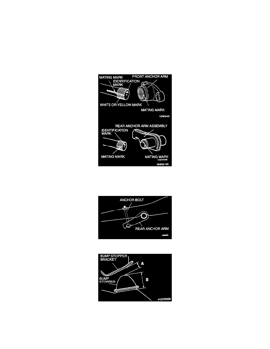
>A< Torsion Bar/Rear Anchor Arm Installation (3 & 5)
1. Check the identification marks at the end of the left and right torsion bars.
R for right side
L for left side
2. When installing the torsion bar, align the white mark on the serrated section of the torsion bar with the mating mark on the anchor arm.
3. Mount the anchor bolt as shown in the illustration, and install the rear anchor arm adjusting nut.
>B< Bump Stopper And Bump Stopper Bracket Clearance Adjustment (-)
NOTE: Dimension A will be (B = 50 mm [2.0 inches]) when the bump stopper is a new pant. When the bump stopper is worn and becomes less
than 50 mm (2.0 inches), dimension A will increase by the decreased amount.
1. With the vehicle in an unladen condition, dimension A from the bump stopper to the bump stopper bracket should be 18 mm (0.7 inch).