
Montero Sport LS 2WD V6-3.0L SOHC (1998)
b.
Use special tool MB990954 to tighten the jam nut as follows:
a.
Tighten the jam nut to 127-196 Nm (94-145 ft/lb), then turn the front hub assembly to run in the bearings.
b.
Loosen the nut completely.
c.
Re-tighten to 25 Nm (18 ft/lb), then loosen approximately 30 degrees.
On 4WD models, measure the hub rotary sliding resistance (hub rotation breakaway torque), using a spring scale as shown. The sliding resistance
specification is 4-19 N (0.9-4.3 lbs.).
If the rotary sliding resistance is not within the specification, use special tool MB990954 to tighten or loosen the jam nut as needed.
7.
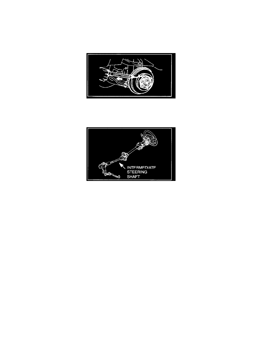
For models produced before 10/29/98 VIN XP028706), refer to TSB-99-37A-001 for intermediate steering shaft replacement and steering gear
backlash adjustment.
8.
Remove the wheel and tire assemblies.
9.
Check the brake disc thickness and and run-out. Refer to Group 35 in the appropriate service manual.
NOTE:
If the brake discs were previously re-surfaced and the front hub end play was not correct in Step 6, the discs may be out of specification.
10.
Worn tires could be a source of steering wheel vibration. Check tire pressure (should be 26 psi when cold) and inspect for tire wear on all four
tires. Particularly check for evidence of tire cupping, indicated by dish-shaped worn spots or bald spots on the tire edges.
Inform the customer of the importance of tire rotation at regular intervals. Suggest tire rotation every 6,000 miles or more frequently as needed for
this type of vehicle.
11.
Check wheel balance on all four wheels. Proper wheel balance is CRITICAL in reducing body vibration. Refer to TSB-00-31-001 REV for wheel
balance adjustment information using hub adapter special tool MB991820.
If possible, perform wheel balance on a Hunter 9700 wheel balancer. Record the radial force variation for each wheel and tire assembly on the
repair order. Mark the location where the wheel and tire assembly was installed on the vehicle on the inside sidewall, for possible future diagnosis.
12.
Reinstall the wheel and tire assemblies.
13.
Test drive the vehicle to confirm if the vibration is minimized. If the vibration is not minimized, go to Step 14.
14.
--> If the vibration is not minimized:
3.0L and 2.4L Models: