
Montero Sport LTD 2WD V6-3.5L SOHC (2000)
SRS Control Unit: Testing and Inspection
WARNING:
1. Never attempt to disassemble or repair the SRS-ECU. If faulty, replace it.
2. Do not drop or subject the SRS-ECU to impact or vibration.
If denting, cracking, deformation, or rust are discovered in the SRS-ECU, replace it with a new SRS-ECU. Discard the old one.
3. After deployment of an air bag, replace the SRS-ECU with a new one.
4. Never use an ohmmeter on or near the SRS-ECU, and use only the special test equipment.
INSPECTION
WARNING: If a dent, crack, deformation or rust is discovered, replace the SRS-ECU with a new one.
-
Check the SRS-ECU and brackets for dents, cracks or deformation.
-
Check the SRS-ECU connector for damage, and the terminals for deformation.
NOTE: Refer to System Diagnosis or inspection of SRS-ECU for other than physical damage.
To inspect and service the SRS after a collision (whether or not the air bags have deployed), perform the following steps.
SRS-ECU MEMORY CHECK
Required Special Tool: MB991502: Scan tool (MUT-II)
CAUTION: Turn "OFF" ignition switch before connecting or disconnecting scan tool MB991502.
1. Connect scan tool MB991502 to the data link connector (16-pin).
2. Read (and write down) all displayed diagnostic trouble codes.
NOTE: If the battery power supply has been disconnected or disrupted by the collision, scan tool MB991502 cannot communicate with the
SRS-ECU Check the battery then check and, if necessary, repair the front wiring harness and the body wiring harness before proceeding.
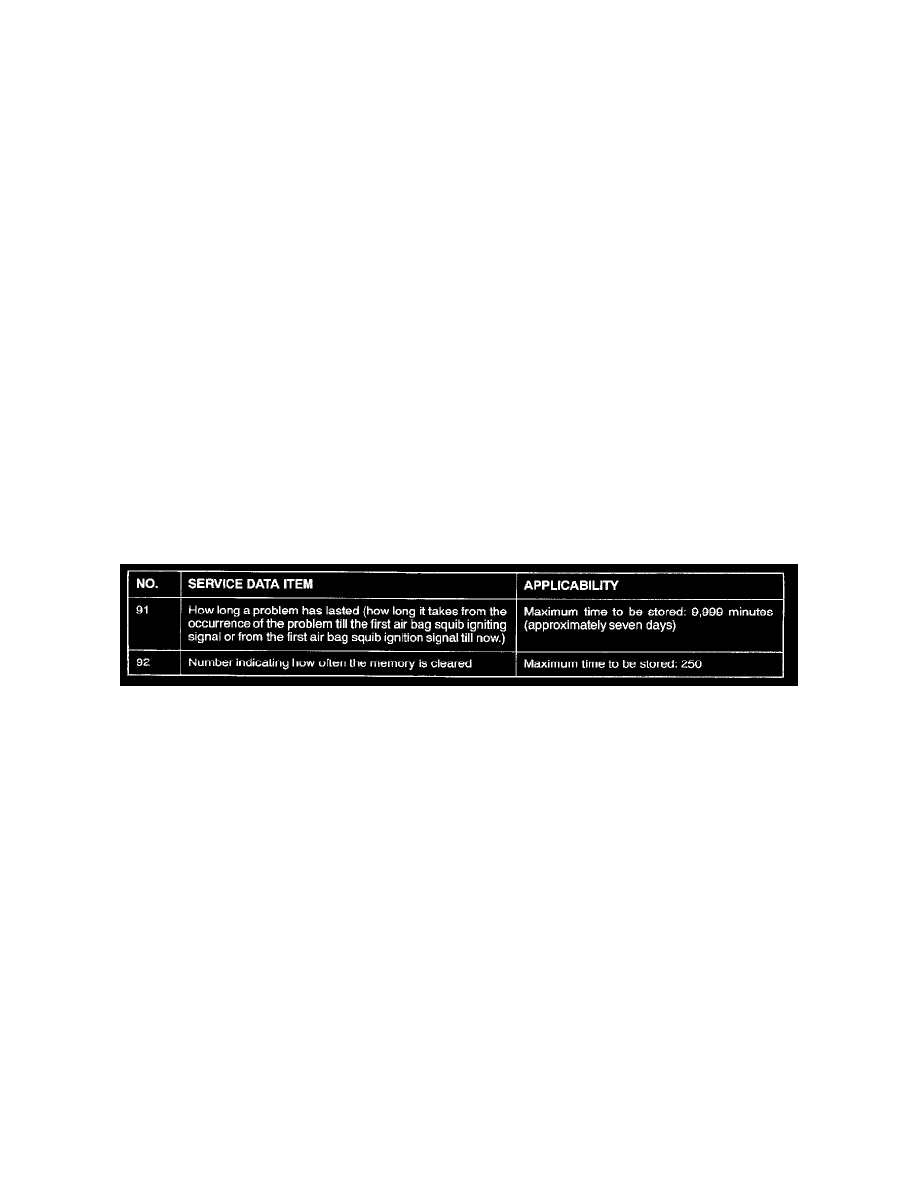
Data List
3. Read the data list (fault duration and how many times memories are erased) using scan tool MB991502.
4. Erase the diagnostic trouble codes and after waiting five seconds or more read (and write down) all displayed diagnostic trouble codes.