
Montero Sport LTD 2WD V6-3.5L SOHC (2000)
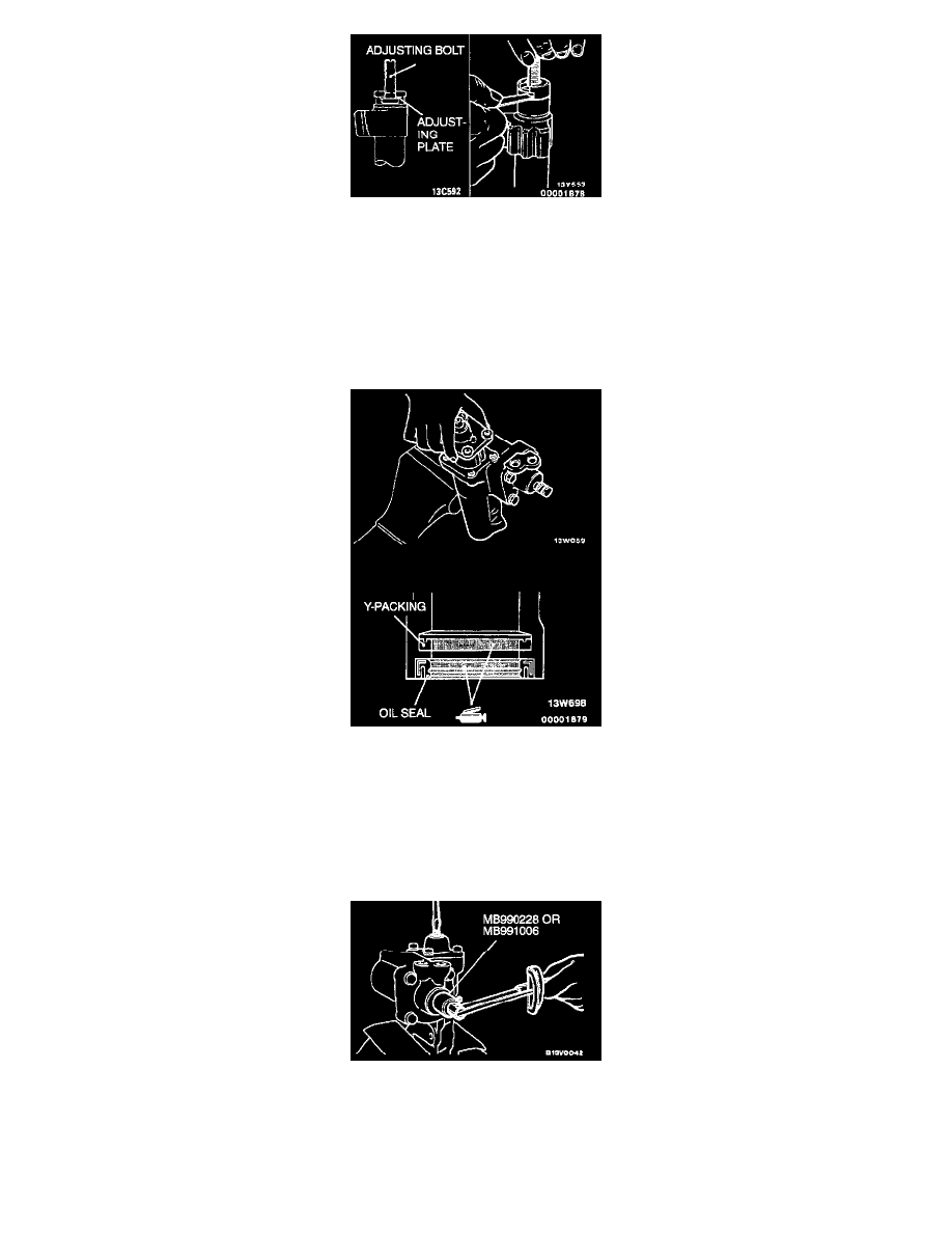
1. Install the adjusting plate so that the beveled part is facing downward.
2. Use a feeler gage to measure the clearance between the adjusting bolt and the cross-shaft.
Standard value: 0.05 mm (0.002 inch)
3. If the clearance exceeds the standard value, replace with a suitable adjusting plate.
>C< Cross-Shaft/Adjusting Bolt Jam Nut Installation
Install the cross-shaft to the side cover, and then temporarily tighten the adjusting bolt jam nut.
>D< Side Cover And Cross-Shaft Assembly Installation
CAUTION: Do not rotate the side cover during installation. Take care not to damage the cross-shaft oil seal.
Install the side cover assembly (with the cross-shaft) to the gear box.
NOTE: Apply the Automatic transmission fluid DEXRON II to the teeth and shaft areas of the rack piston, and apply multipurpose grease to the
oil seal lip.
>E< Mainshaft Total Breakaway Torque Adjustment
CAUTION: Adjust by turning the adjusting bolt so that the breakaway torque at the center position of the rack piston is approximately 0.2 Nm
(1.8 inch lbs.) higher than the values at the both ends of the rack piston.
1. While turning the adjusting bolt, measure the mainshaft total breakaway torque by using special tool MB990228 or MB991006.
Standard value: 0.69-1.28 Nm (6-12 inch lbs.)
2. Tighten the adjusting bolt jam nut to the specified torque.