
Montero Sport LTD 4WD V6-3.5L SOHC (1999)
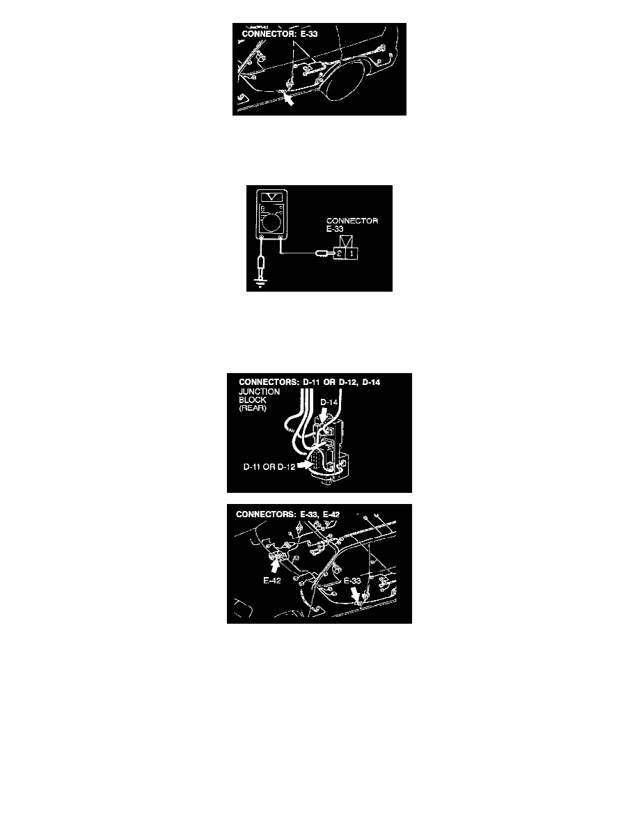
STEP 4. Check the driver's side door switch connector for damage.
If harness connector E-33 is damaged, repair or replace it.
If harness connector E-33 is in good condition, go to Step 5.
STEP 5. Check the input signal from the driver's side door switch.
1. Disconnect driver's side door switch connector E-33 and measure at the harness side.
2. Measure the voltage between terminal number 2 and ground.
Voltage should be approximately 5 volts. If approximately 5 volts, go to Step 7.
If not approximately 5 volts, go to Step 6.
STEP 6. Check the harness wires between driver's side door switch connector E-33 and ETACS-ECU connector D-11 or tone alarm-ECU
connector D-12.
If the harness wires between driver's side door switch connector E-33 and ETACS-ECU connector D-11 or tone alarm-ECU D-12 are damaged, repair
them. Check that the malfunction is eliminated.
If the harness wires are in good condition, go to Step 7.
NOTE: After inspecting junction block connector D-14 and intermediate connector E-42, inspect the wire. If junction block connector D-14 and
intermediate connector E-24 are damaged, repair or replace them. Refer to GENERAL Harness Connector Inspection.
STEP 7. Check the key reminder switch continuity.
1. Remove the driver's side under cover.
2. Remove the column covers, lower and upper.
3. Disconnect wiring connector D-16 from the key reminder switch and measure at the key reminder switch side.