
Montero Sport LTD 4WD V6-3.5L SOHC (1999)
If ETACS-ECU or tone alarm-ECU connector D-11 or D-12 is damaged, repair or replace it.
If ETACS-ECU or tone alarm-ECU connector D-11 or D-12 is in good condition, go to Step 14.
STEP 14. Check the harness wires between the ETACS-ECU connector D-11 or tone alarm-ECU connector D-12 and ignition switch (IG1).
If the harness wires between the ETACS-ECU connector D-11 or tone alarm-ECU connector D-12 and ignition switch (IG1) are damaged, repair them,
go to Step 15.
NOTE: After inspecting junction block connector D-08, inspect the wire. If junction block connector D-08 is damaged, repair or replace it. Refer to
Harness Connector Inspection.
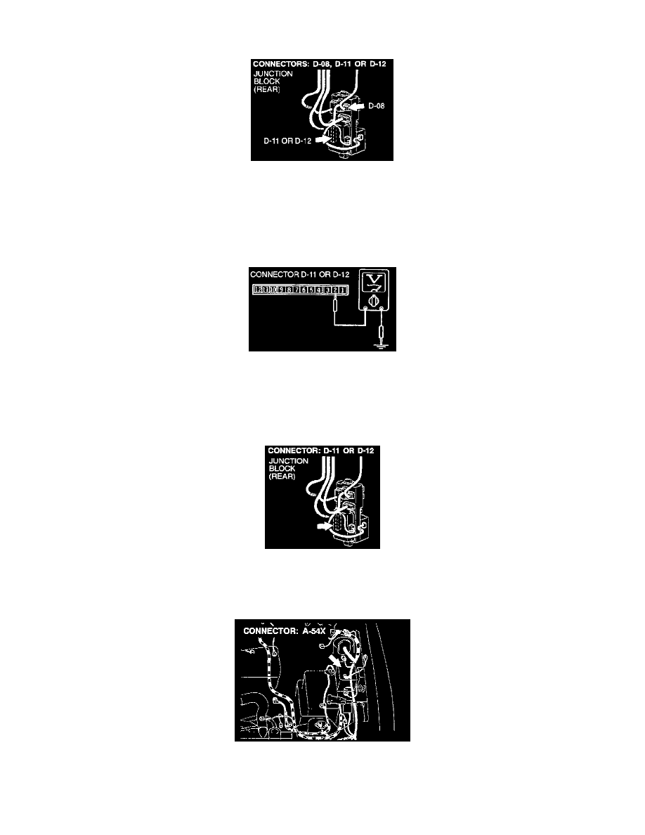
STEP 15. Check the ETACS-ECU or tone alarm-ECU power supply circuit.
1. Remove the ETACS-ECU or tone alarm-ECU and measure at the junction block side (connector D-11 or D-12.)
2. Measure the voltage between terminal number 2 and body ground.
Voltage should be approximately 12 volts (battery positive voltage).
If any circuit check made at connector D-11 or D-12 does not meet specifications, go to Step 16.
If any circuit check made at connector D-11 or D-12 meets specifications, check that the malfunction is eliminated.
STEP 16. Check the harness wires between ETACS-ECU connector D-11 or tone alarm-ECU connector D-12 and fusible link number 6.
If the harness wires between ETACS-ECU connector D-11 or tone alarm-ECU connector D-12 and fusible link number 6 are damaged, repair them.
Then go to Step 17.