
Montero Sport LTD 4WD V6-3.5L SOHC (1999)
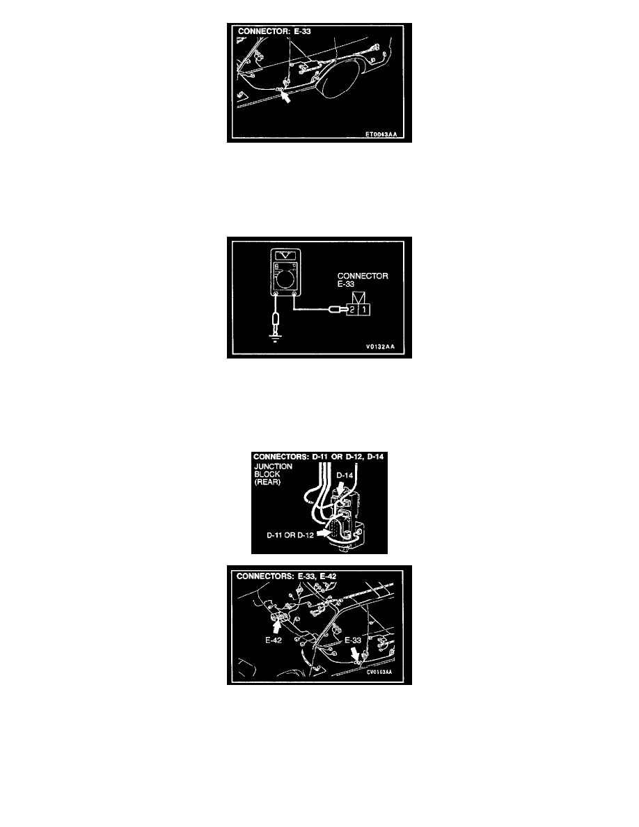
STEP 4. Check the driver's side door switch
connector for damage.
If harness connector E-33 is damaged, repair or replace it.
If harness connector E-33 is in good condition, go to Step 5.
STEP 5. Check the driver's side door switch input circuit.
1. Disconnect the driver's side door switch connector E-33 and measure at the harness side.
2. Measure the voltage between terminal number 2 and ground.
-
Voltage should be approximately 5 volts.
If approximately 5 volts, check that the malfunction is eliminated.
If not approximately 5 volts, go to Step 6.
STEP 6. Check the harness wires between driver's side door switch connector E-33 and ETACS-ECU connector D-11 or tone alarm-ECU
connector D-12.
If the harness wires between driver's side door switch connector E-33 and ETACS-ECU connector D-11 or tone alarm-ECU D-12 are damaged, repair
them. Check that the malfunction is eliminated.
If the harness wires are in good condition, go to Step 7.
NOTE: After inspecting junction block connector D-14 and intermediate connector E-02, inspect the wire. If junction block connector D-14 and