
Montero Sport LTD 4WD V6-3.5L SOHC (1999)
CIRCUIT OPERATION
-
A/T control relay supplies the battery voltage to each solenoid valve (terminal 9 and terminal 10).
-
Each solenoid valve closes when energized (on), and opens when de-energized (oft). The PCM energizes or de-energizes each solenoid valve,
based on inputs data from sensors such as throttle position sensor, PNP, stoplight VSS, PG-A, PG-13, ATF temperature etc.
-
The PCM provides the ground to energize each solenoid. The ground time is displayed in percent.
-
As each solenoid is energized or de-energized, it influences hydraulic pressure in the transmission applying and releasing elements.
DTC SET CONDITIONS
-
If the resistance value for a solenoid valve circuit is greater than 3.5 Ohms for 4 seconds at 100°C (212°F) or less than 2.6 Ohms for 4 seconds at
100°C (212°F), it is judged that there is a short circuit or an open circuit in the solenoid valve and the associated diagnostic trouble code is
displayed. The transmission is locked into 3rd gear as a fail-safe measure, and the "N" range light flashes at a frequency of 1 Hz.
TROUBLESHOOTING HINTS
The most likely causes for these codes to be set:
-
Malfunction of each solenoid valve
-
Damaged connector
-
Malfunction of the PCM
DIAGNOSIS
Required Special Tool: MB991502: Scan Tool (MUT-II)
CAUTION: To prevent damage to scan tool MB9911502, make sure the ignition switch is "OFF" before connecting or disconnecting scan tool
MB9911502.
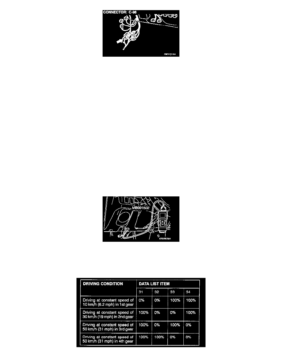
STEP 1. Using Scan Tool MB991502, Check Data List.
1. Check the following items in the data list.
a. Item 31: Low-reverse solenoid valve duty percent
b. Item 32: Underdrive solenoid valve duty percent
c. Item 33: Second solenoid valve duty percent
d. Item 34: Overdrive solenoid valve duty percent