
Montero Sport LTD 4WD V6-3.5L SOHC (1999)
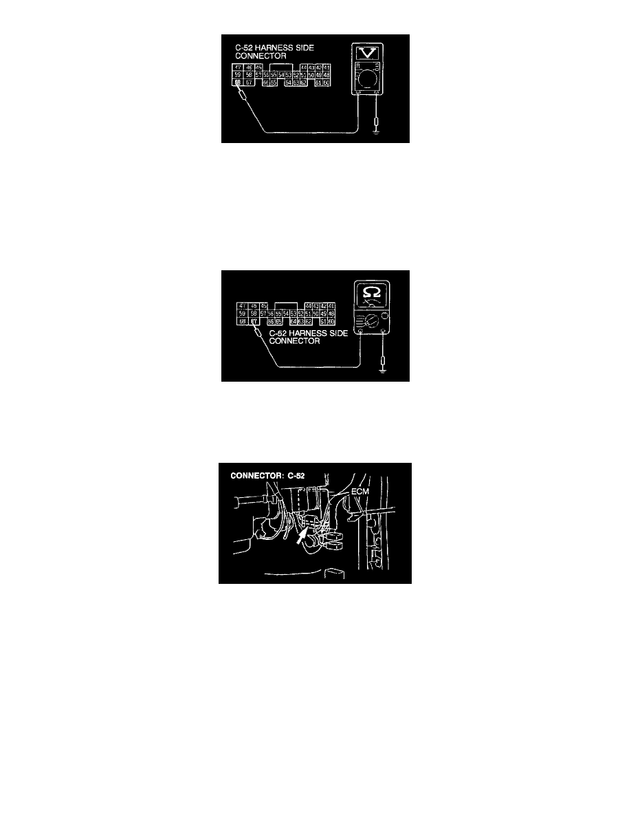
3. Measure voltage between terminal 68 and ground.
-
The voltage should be 8 volts or more.
4. Turn the ignition switch "OFF"
If within specifications go to Step 2.
If not within specifications, repair the harness wire between the ECM connector C-52 and the starter relay connector A-50X. Then
confirm that the malfunction symptom is eliminated.
STEP 2.
Check the circuit at the ECM connector C-52.
1. Disconnect connector C-52 and measure at the harness side.
2. Check for continuity between terminal 67 and ground.
-
There should be continuity (0 Ohm).
If continuity, go to Step 3.
If no continuity, repair the harness wire between the ECM connector C-52 and the ground. Then confirm that the malfunction symptom
is eliminated.
STEP 3.
Check harness connector C-52 at the ECM for damage.
If harness connector C-52 is damaged, repair or replace it.
Refer to Harness Connector Inspection.
If harness connector C-52 is in good condition, replace the ECM. Then confirm that the malfunction symptom is eliminated.
Diagnostic Troubleshooting Strategy
Use these steps to plan your diagnostic strategy. If you follow them carefully, you will be sure that you have exhausted most of the possible ways to find
an ignition switch fault.
1. Gather information from the customer.
2. Verify that the condition described by the customer exists.
3. Find the malfunction by following the Symptom Chart.
See: Ignition Switch Diagnosis/Symptom Chart
4. Verify malfunction is eliminated.
Symptom Chart