
Montero Sport LTD 4WD V6-3.5L SOHC (1999)
STEP 1. Check the input signal from the driver's side door switch.
<Vehicles with ETACS-ECU>
CAUTION: To prevent damage to scan tool MB991502, make sure that the ignition switch is "OFF" before connecting or disconnecting the scan tool
MB991502.
1. Connect scan tool MB991502 to the data link connector.
2. Check that the tone alarm of the scan tool MB991502 sounds when the driver's side door is opened.
If the tone alarm of the scan tool MB991502 does not sound, the input signal from the driver's side door switch is not normal. Go to Step 2.
If the tone alarm of the scan tool MB991502 sounds when the driver's side door is opened [front door switch (LH) is turned to ON], the signal
from the driver's side door switch is normal. Replace the ETACS-ECU. Check that the malfunction is eliminated.
<Vehicles with tone alarm-ECU> Go to Step 2.
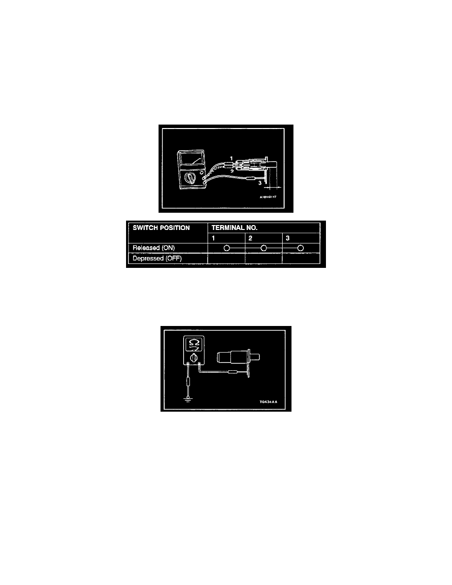
STEP 2. Check the driver's side door switch.
1. Remove the driver's side door switch. Refer to Door.
2. Check continuity at the driver's side door switch.
If the driver's side door switch is in good condition, go to Step 3.
If the driver's side door switch is defective, replace it. Check that the malfunction is eliminated.
STEP 3. Check the driver's side door switch ground circuit system.
Check the continuity between the driver's side door switch body (metal section) and ground.
-
There should be continuity (0 Ohm).
If continuity, go to Step 4.
If no continuity, repair the harness wire or connector. Then go to Step 5.