
Montero Sport LTD 4WD V6-3.5L SOHC (1999)
STEP 3. Check the driver's side door switch ground circuit system.
Check continuity between the driver's side door switch body (metal section) and ground.
-
There should be continuity (0 Ohm).
If continuity, go to Step 4.
If no continuity, repair or replace the switch. Check that the malfunction is eliminated.
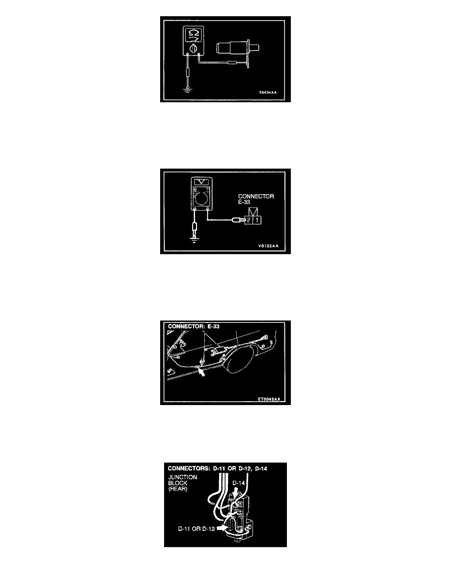
STEP 4. Check the input signal from the driver's side door switch.
1. Disconnect driver's side door switch connector E-33 and measure at the harness side.
2. Measure the voltage between terminal number 2 and ground.
Voltage should be approximately 5 volts.
If approximately 5 volts, check that the malfunction is eliminated.
If not approximately 5 volts, go to Step 5.
STEP 5. Check the driver's side door switch connector for damage.
If harness connector E-33 is damaged, repair or replace it.
If harness connector E-33 is in good condition, go to Step 6.