
Montero Sport LTD 4WD V6-3.5L SOHC (1999)
NOTE: Dimension A will be (B = 50 mm [2.0 inches]) when the bump stopper is a new part. When the bump stopper is worn and becomes
less than 50 mm (2.0 inches), dimension A will increase by the decreased amount.
2. If dimension A is not 18 mm (0.7 inch), adjust the rear anchor arm adjusting nut.
>D< Shock Absorber Installation
Install the shock absorber so that the distance (A) shown in the illustration is at the standard value.
Standard value (A): 1 - 2 mm (0.04 - 0.08 inch)
INSPECTION
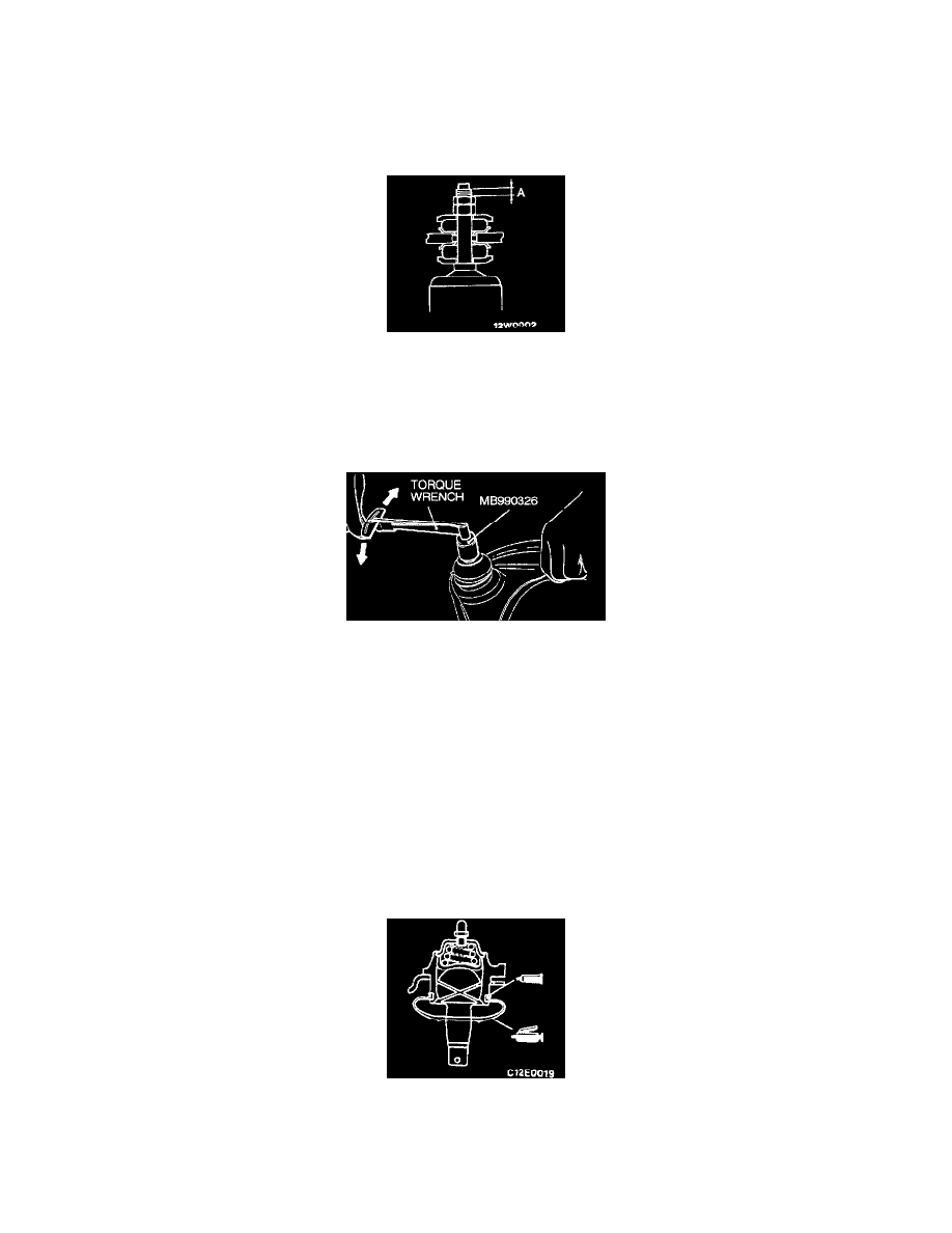
Upper Arm Ball Joint Breakaway Torque Check
1. After shaking the upper arm ball joint assembly stud several times, install the nut to the stud and use the special tool MB990326 to measure the
breakaway torque of the upper arm ball joint assembly.
Standard value: 0.8 - 3.4 Nm (7.1 - 30.1 inch lbs.)
2. When the measured value exceeds the standard value, replace the upper arm ball joint.
3. When the measured value is lower than the standard value, check that the ball joint turns smoothly without excessive play. If not, it is possible to
use that upper arm ball joint.
Upper Arm Ball Joint Dust Cover Check
1. Press the dust cover with a finger to check whether the dust cover is cracked or damaged.
2. If dust cover is cracked or damaged, replace the upper arm ball joint. Cracked or damaged dust cover may cause damage to the ball joint. In
addition, if the dust cover is damaged during service work, replace the dust cover.
Upper Arm Ball Joint Dust Cover Replacement
Only when dust cover is damaged accidentally during service work, replace the dust cover as follows:
1. Apply multipurpose grease to the interior of the dust cover and the upper arm ball joint.
2. Secure the dust cover to the upper arm ball joint with ring.
3. Press the dust cover with a finger to check whether the dust cover is cracked or damaged.